Bauanleitung, Assembly instructions, Notice de montage
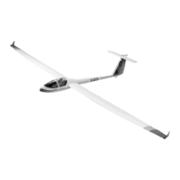
Calif A21 S
2
3034
No.
Technische Daten
Spannweite: ca. 4120 mm
Länge: ca. 1510 mm
Gesamtflächeninhalt: ca. 62 dm
2
Fluggewicht : ca. 5000 g
Flügelprofil: SD 7062
Nicht enthaltenes Zubehör siehe Beilageblatt
Werkzeuge und Hilfsmittel siehe robbe Hauptkatalog
Allgemeine Hinweise für den Bauablauf
Verschaffen Sie sich vor Baubeginn in Verbindung mit den
Abbildungen und den Kurztexten einen Überblick über die
Reihenfolge des Bauablaufs.
Denken Sie daran, daß Reklamationen nur vor Baubeginn
und nicht nachdem die Teile schon bearbeitet wurden, von
uns anerkannt werden können.
Wenn nicht anders erwähnt, wird mit Epoxy geklebt. Bei ver-
schiedenen Klebestellen, insbesondere beim Einbau der
Spanten, empfiehlt es sich, das Harz z. B. mit Micro-Ballons
einzudicken.
Alle Klebestellen vor dem Klebevorgang mit Schleifpapier
aufrauhen.
Das Auffinden der Stanzteile erleichtert die
Identifikationszeichnung „0“ auf Seite 5. Stanzteile entspre-
chend kennzeichnen und bohren, dann erst austrennen.
Hinweise zur Fernsteueranlage
Als Fernsteuerung benötigen Sie eine Anlage mit 9 Kanälen
und 10 Servos.
Orientieren Sie sich vor Baubeginn über die Einbaumöglich-
keit der zu verwendenden Fernsteuerung.
Sollte eine andere, als die von uns vorgeschlagene
Steuerung verwendet werden, können Sie sich nach dem
Einbauschema richten.
Maßdifferenzen sind von Ihnen selbst auszugleichen.
Caractéristiques techniques
Envergure 4120 mm environ
Longueur 1510 mm environ
Surface alaire totale 62 dm
2
environ
Poids en ordre de vol planeur approx. 5000 g
Profil de l’aile SD 7082
Accessoires non contenus dans la boîte de construction,
cf. le feuillet joint
Outillage et accessoires de montage, cf. Catalogue
général robbe
Recommandations générales concernant la construction
Avant d’entreprendre la construction, lire attentivement les
textes explicatifs en vous reportant aux illustrations afin de
vous faire une idée d’ensemble de l’ordre des séquences
d’assemblage.
Ne pas oublier que nous n’acceptons de réclamation qu’an-
térieurement à la construction du modèle et non pas lorsque
les pièces ont été traitées.
Sauf mention contraire, coller avec de la colle époxy. Pour
divers emplacements, particulièrement en ce qui concerne
les couples, il est recommandé d’épaissir la résine avec des
micro-ballons par exemple.
Poncer tous les emplacements destinés à recevoir de la colle
avec du papier de verre fin avant d’appliquer la colle.
L’identification des éléments estampés est facilitée par le
schéma “0” spécifique de la page 5. Repérer les éléments
estampés en conséquence et les percer avant de les détach-
er de leur support.
Recommandations concernant l’ensemble de radiocom-
mande
L’ensemble de radiocommande recommandé doit disposer
de 9 voies et être en mesure d’asservir 10 servos.
Avant d’entreprendre la construction, il faut disposer de
l’ensemble de réception afin de déterminer les possibilités
d’implantation.
Specification
Wingspan: approx. 4120 mm
Length: approx. 1510 mm
Total surface area: approx. 62 dm
2
All-up weight: approx. 5000 g
Wing section: SD 7062
Please see the separate sheet for details of essential
items not included in the kit. The main robbe catalogue
contains details of tools and aids to building.
Sequence of assembly
Please read through the building instructions, referring to the
illustrations all the time, so that you have a clear idea how
the model goes together before you start building.
Bear in mind that we cannot consider complaints about any
part of the kit which you have already worked on, so check
all the components carefully right at the outset.
Epoxy is to be used for all joints in this model unless specif-
ically stated otherwise. In some cases it is advisable to thick-
en the resin with micro-balloons or similar filler powder; this
applies in particular to the joints between the bulkheads and
the fuselage.
Roughen all joint surfaces with abrasive paper before apply-
ing glue.
The identification drawing „0“ on page 5 is designed to help
you identify the die-cut parts. Mark the numbers on the die-
cut parts and drill holes at the marked points before you
separate the parts from the sheet.
Radio control system
For the Calif you will need an 9-channel radio control system
with 10 servos.
Check that your system components will fit as shown before
you start installing the equipment.
 Loading...