Do you have a question about the ROBBE Calif A21 S and is the answer not in the manual?
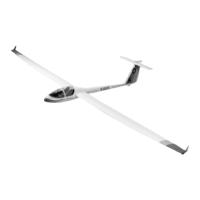
Details on the model's wingspan, length, and total surface area.
Information regarding the model's all-up weight and wing section profile.
Read instructions and illustrations thoroughly before commencing construction.
Prepare all gluing surfaces with sandpaper and use identification drawings for parts.
Specifies a 9-channel radio control system with 10 servos for optimal model operation.
Guidance on fitting the twin-wheel retract unit, referring to its separate instructions.
Instructions on using a heat gun to re-tighten covering film slackened by temperature changes.
Specifies that directions (e.g., 'right') are viewed from the tail of the model looking forward.
Detailed list of all components and quantities provided in the Calif A21 S model kit.
Glue reinforcement doublers to the rear main bulkhead, ensuring accurate alignment of openings.
Connect bulkhead, side panels, and servo frame to create the RC installation structure.
Position and glue the prepared main bulkhead onto the assembled fuselage frame.
Lists components needed: longitudinal former, spacer rails, retaining plate, and mounting blocks.
Place servo in former, glue strips, sand servo lug, and secure mounting blocks with cyano.
Mark, drill, and attach retaining strap to blocks using self-tapping screws.
Place servo frame, align horizontally, and glue with thickened epoxy for stability.
Insert switch support, longitudinal former, and front half-former into their respective fuselage positions.
Align and securely glue all internal wooden parts to each other and to the fuselage.
Mount the servos and the electrical switch into their designated housing and supports.
Place cockpit insert, check fit, sand edges if needed, and glue dowel in place.
File a precise slot in the fuselage to accept the locating dowel for snug fit.
Drill holes through cockpit insert and wing root fairing, then enlarge fuselage holes.
Solder sleeve to steel rod, insert into guide tube, and fit assembly into fuselage and fairing holes.
Glue guide tube flush to fuselage, cut excess, and position sleeve for reliable latch operation.
Mark rod exit, slide sleeve, cut rod, and solder ball for canopy latch activation.
Install any desired scale interior details for the cockpit at this stage of assembly.
Protect fuselage, fit cockpit insert, trim canopy for fit, and glue to insert.
Bend elevator joiner rod ends at right angles and attach ball-end bolt and collet assembly.
Mark and drill holes in elevators, relieving surfaces for unrestricted movement.
Glue the completed elevator joiner rod securely into the prepared holes in the elevators.
Connect extension lead, trim servo arm, place servo in fin, drill, secure, and route cable.
Fix tailplane to fin, connect pushrod to servo arm, and check elevator travel for obstruction.
Mount the clevis and cross-lever unit onto the elevator servo output arm.
Drill tailpost, cut ring-screw to length, and fit it, ensuring correct distance from center.
Sand the extreme bottom edge of the rudder horizontally to ensure proper fit and alignment.
Glue brass sleeves and facing strip to the rudder leading edge for secure pivoting.
Offer rudder to fin, mark recess location for ball-end bolt, and file as needed.
Bend pivot rod, insert to secure rudder, check elevator linkage movement, and glue ring-screw.
Mark and drill holes for rudder horns (ring-screws) on both rudder sides at an angle.
Cut, countersink, install ring screws into rudder, and secure with cyanoacrylate.
Cut braided wires, fit brass sleeves through ring screws, crimp, and solder for rudder actuation.
Thread the two braided wires forward through the fuselage to connect to the rudder servo.
Position rudder, mark slots, fit top pivot rod, check movement, and ensure clearance.
Screw clevises onto couplers, connect to servo, tension wires, and mark correct length.
Double wires, disconnect clevises, fit couplers, solder joints, and trim excess wire.
Drill an 8 mm diameter hole centrally in the fuselage at the specified point.
Shape hardwood block, drill 3.2 mm hole, and glue in a 120 mm guide tube.
Drill block/tube, connect pushrod to servo, glue block, and adjust servo for reliable towline release.
Cut out templates for the retract wheel doors from the provided sheet.
Lay templates inside fuselage against bulkheads, optionally fixing with rubber cement.
Drill cut lines, trim supports, glue in place, mark and cut panels for doors.
File notches in wheel wells for pin hinges and drill holes for hinge supports.
Glue rails/strips to doors, assemble pin hinges, bend S-hooks, and glue them to doors.
Place doors in fuselage, align, tape, and glue pin hinges to fuselage interior.
Drill supports, connect rubber bands to S-hooks, wrap around strips, and check reliable door opening/closing.
Degrease/roughen rods, slide into sockets, fit screws, pull rods out 1mm, and tighten.
Fit tailplane, plug in wings, align, mask fuselage, apply epoxy to sockets, and allow to cure.
Loosen screws, withdraw wings, and separate ailerons, camber-changing flaps, and brake flaps.
Install aileron servos with Servo-Locks, glue base, cut servo arm, and secure.
Tape ailerons neutral, set servos neutral, and offset servo arms for differential travel.
Fit Servo-Lock covers and repeat for camber-changing and brake flap servos.
Connect brake flap servos to the same output using a Y-lead; ensure they rotate in the same direction.
Drill holes for incidence pegs and wing root rib, fit pegs, mask fuselage, plug in wings, align, and epoxy.
Drill winglets, mark hole positions, grease screw, epoxy rivet nut, and glue rear dowel.
Hold winglets against wing panels and secure them using the M2.5 x 10 screws.
Uncoil aerial, fit in tube or outside fuselage, pack receiver/battery, and connect system components.
Assemble model, connect servos, attach tailplane, check CG (approx. 55 mm), and add ballast if needed.
Connect servos, switch on RC, check neutral settings, rotation direction, and brake flap sync.
Select mixer program, tune travels to stated values, and mark servo connectors.
Get assistant for launch, take control, check response, and trim immediately.
Launch with good thrust, take control, and trim the model immediately if required.
Gain safe height, check response to controls, and verify flap effects.
Observe model carefully, adjust linkages after first landing to center trims.