INSTALLATION INSTRUCTIONS (CON’T)
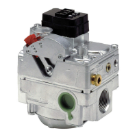
4. If it’s not already installed, a drip leg (sediment trap) must be added
to the gas supply line to the control. (See gure below). All piping
must comply with local codes and ordinances and with Naonal
Fuel Gas Code (ANSl.1/NFPA, No. 54).
5. Using pipe thread compound suitable for gas being used, apply a
small amount on the male pipe threads. (Do not use Teon tape or
Teon compound). Leave the rst two threads clean. Never use
compound on female threads as it might be pushed into the
control body.
6. The gas valve is mul-posion and can be mounted in any posion
(except upside down) without aecng its operaon.
7. Install gas valve so gas ow conforms with the inlet and outlet of
the control.
8. DO NOT insert any object other than suitable pipe or tubing in the
inlet or outlet of this control. Internal damage may occur and result
in hazardous condion. A backup wrench should only be used on
the wrench boss provided for this purpose (see drawing), never on
body of the control, as this could distort the casng. NOTE: Do not
overghten any pipe connecons, as this could crack the valve body.
A valve with a cracked valve body will not be warraned.
PILOT TUBING
NOTE: Some hot surface applicaons use the pilot outlet, if so proceed
as directed below. If not used install pilot outlet tubing plug packaged
in the 720-079 gas valve kit then proceed to “wiring”.
1. Make sure tubing is free of burrs and dirt.
2. We strongly recommend that the pilot orice be checked and
cleaned if necessary at this me.
3. Connect pilot tubing into the control using ng provided, and
ghten for a gas-ght seal.
WIRING
DO NOT short gas valve terminals. This will damage wall thermostat
and void warranty.
Check the system for the proper transformer by comparing the VA
rangs of the transformer and the system. The system rang is
determined by mulplying the voltage draw mes the amp draw.
Normally 20VA transformers are sucient for heang only applicaons
and 40VA for heang/cooling applicaons.
NOTE: Improper transformer VA rang will cause errac system
operaon.
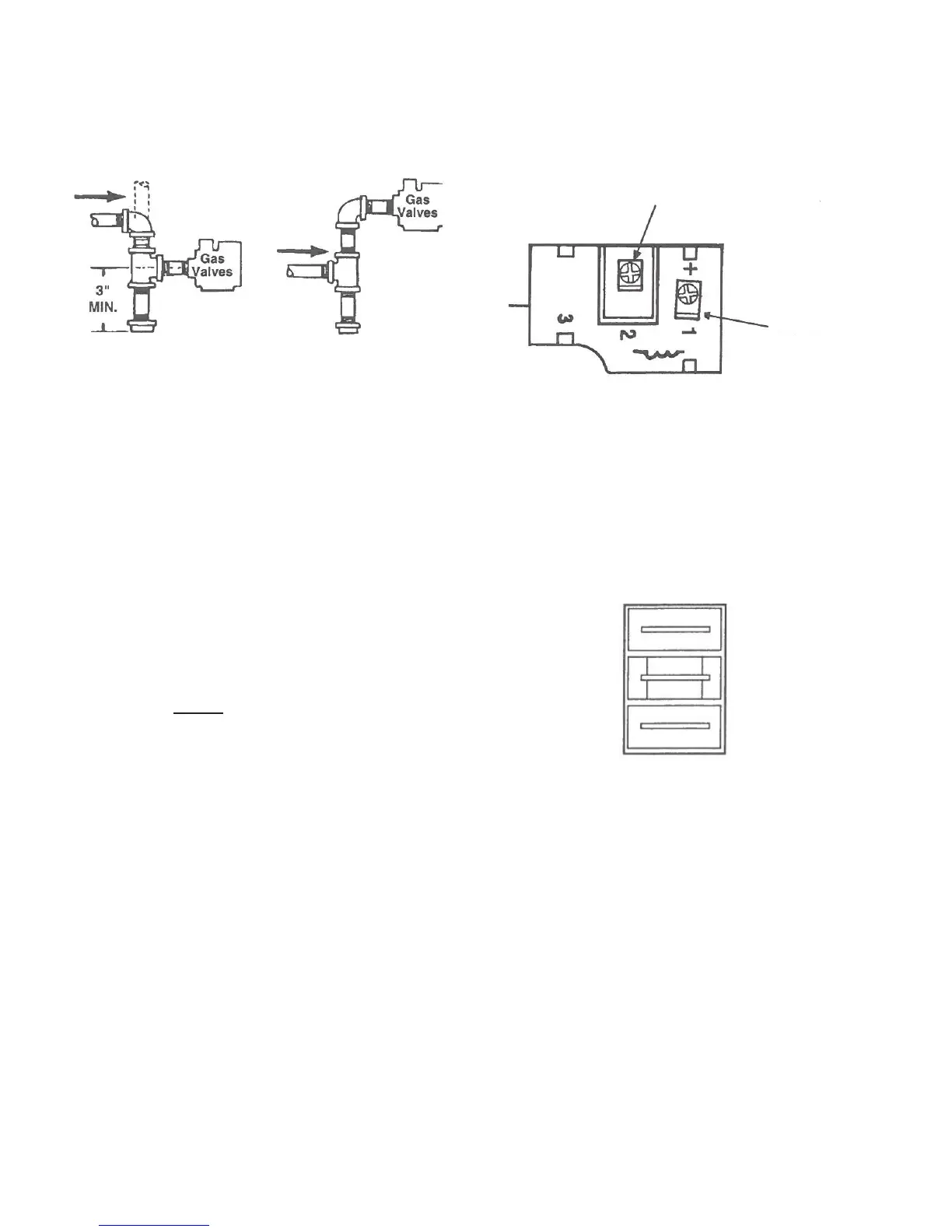
7200 DER MODELS
1. Connect the gas valve terminal #1 to the “valve” terminal on the
ignion control module. See wiring diagram shown below.
2. Connect the gas valve terminal #2 to the “valve” terminal on the
ignion control module. See wiring diagram shown below.
7200 IPER MODELS
3. Locate the white wire terminal adaptor (jumper) that is included
with the gas valve.
4. Connect white wire terminal adaptor to the “M” and “P” terminals
on the gas valve.
5. Determine which wire was connected to the “main valve” terminal
on the original valve. Connect this wire to the remaining terminal on
the white wire terminal adaptor.
PRESSURE REGULATOR VENT
The 720-079 has a built-in Vent Limiter. The regulator vent is taped 1/8”
tubing if vent tubing is required. CAUTION: If bleed tubing is used, do
not allow main burner or pilot ame impingement on the tubing as this
will eventually cause clogging of the tubing and improper regulator
operaon. If bleed tubing is not used the regulator vent must be
properly shielded from moisture.
LEAK TEST
Leak test with a soap soluon aer installing with main burner on. Coat
pipe and tubing joints, gasket, etc. with soap soluon. Bubbles indicate
leaks.
TO “GROUND”
ON IGN. MODULE
TO “VALVE”
ON IGN. MODULE
M
P
 Loading...