Customer Service Telephone 1.800.304.6563
Customer Service Facsimile 1.800.426.0804
HVACCustomerService@robertshaw.com
Robertshaw®, Ranco®, Paragon® and Uni-Line® are
trademarks of Robertshaw, its subsidiaries and/or
affiliated companies. All other brands mentioned
may be the trademarks of their respective owners.
For Technical Service
Telephone 1.800.445.8299
Facsimile 1.630.260.7294
TechnicalService@robertshaw.com
www.uni-line.com
www.robertshaw.com
©2014 Robertshaw
09/14 –1-810 RevC
WARNING
Servicing of gas controls, appliance and systems must be
performed by qualied service personnel only.
CAUTION: If control has been exposed to water in any way, it must be
replaced. If gas valve fails to shut o, do not turn o electrical power.
Turn o gas supply allowing fan or circulang pump (if so equipped) to
connue running unl system has cooled. Replace control.
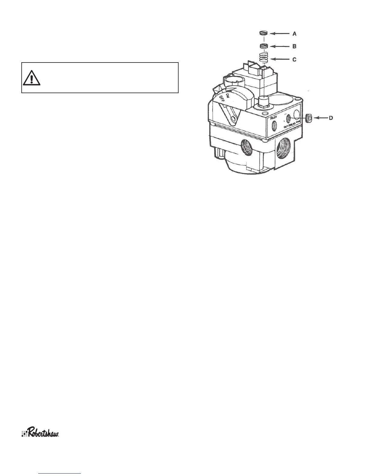
PRESSURE REGULATOR ADJUSTMENTS
Adjustment of the pressure regulator is not normally necessary since it
is preset at the factory. However, eld adjustment may be accom plished
as follows:
NOTE: Manometer aachment may be accomplished at pressure tap
plug, above control outlet, as shown in gure to the right. If using inlet
pressure tap to measure incoming pressure. See drawing on rst page.
1. Manometer or gauge aachment may be accomplished at
pres sure tap plug (D).
2. Remove regulator adjustment screw cap (top of control - A).
3. With small screwdriver, rotate adjustment screw (B) “clockwise”
to increase, or “counterclockwise” to decrease pressure to comply
with manufacturer’s specicaons.
4. Replace regulator adjustment screw cap (A).
REGULATOR CONVERSION
CAUTION: Main burner and pilot orices must be changed when
regulator is converted from one type of gas to another.
The 720 series valves can be converted from natural to L.P. by installing
the enclosed conversion kit.
1. Turn o gas and electricity to appliance.
2. Remove sloed cap (A), adjusng screw (B), and natural gas spring
not color coded - (C), from control.
3. Install new L.P. spring - color coded with a black strip.
4. Install new adjusng screw (B).
5. Aach manometer or pressure gauge at the outlet pressure tap (D).
6. Turn gas and electricity on.
7. Turn room thermostat to call for heat.
8. With burner on, adjust screw (B) to supply L.P. gas to pressure as
recommended by the appliance manufacturer.
9. If adjusng screw (B) reaches its maximum depth (booms out)
before recommended pressure seng is reached, turn screw
counterclockwise unl pressure drops slightly (approximately 0.1”
W.C.) WARNING: Do not stretch or alter spring.
10. Turn o gas and electricity to appliance.
11. Remove manometer or pressure gauge and reinstall pressure tap
outlet plug (D).
12. lnstall new red sloed cap in place of (A).
13. Turn gas and electricity on.
SERVICE INSTRUCTIONS
14. With burner operang, immediately check all ngs for leaks with
soap soluon. Bubbles indicate leaks that must be corrected.
15. Aach label to show control has been converted to L.P.
16. Set room thermostat to desired temperature.
 Loading...