8-2-2
'
IN
CASE
OF
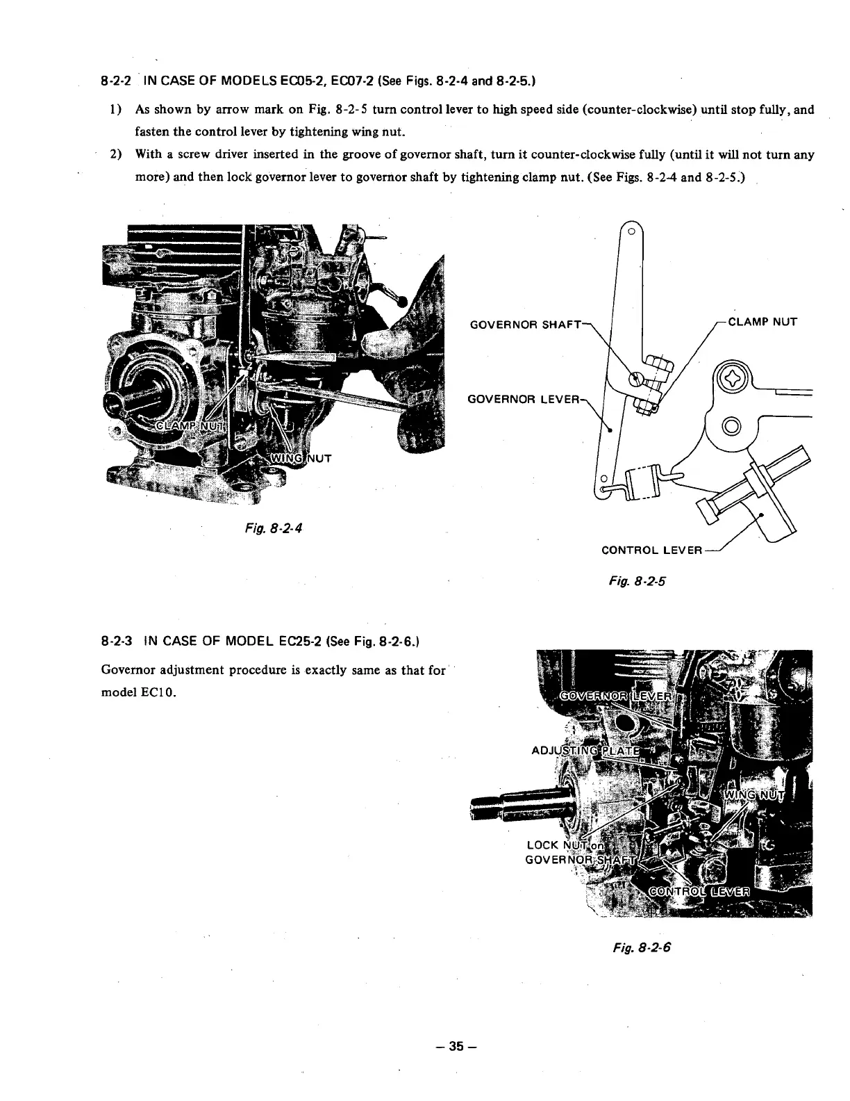
MODELS EC05-2, EC07-2
(See
Figs.
8-2-4
and
8-2-5.)
1)
As
shown by arrow mark on Fig.
8-2-
5
turn control lever to high speed side (counter-clockwise)
until
stop fully, and
fasten the control lever
by
tightening wing nut.
2)
With a screw driver inserted in the groove of governor shaft, turn it counter-clockwise fully (until it
will
not turn any
more) and then lock governor. lever to governor shaft by tightening clamp nut. (See Figs.
8
-24
and
8
-2-5.)
GOVERNORSHAFT
\I
GOVERNOR
Fig.
8-2-
4
Fig.
8-2-5
8-2-3
IN
CASE
OF
MODEL EC25-2
(See
Fig.
8-2-6.)
Governor adjustment procedure
is
exactly same as that for
model
EC10.
LCLAMP
NUT
Fig.
8
-2-
6
-
35
-