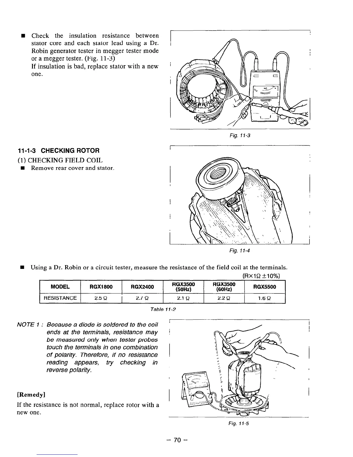
W Check the insulation resistance between
stator core and each stator lead using a Dr.
I
i
Robin generator tester in megger tester mode
I
or a megger tester. (Fig. 11-3)
If insulation is bad, replace stator with a new I
one.
11-l -3 CHECKING ROTOR
(1) CHECKING FIELD COIL
W Remove rear cover and stator.
n
Using a Dr. Robin or a circuit tester, measure the resistance of the field coil at the terminals.
Fig. 1 l-3
Fig. 17-4
(RxlR MO%)
MODEL RGX1800 RGX2400 1 RGX3500
RGX3500
I
(50Hz) 1
(60Hz)
RGX5500
RESISTANCE
2.5 C-2
2.7 R
2.1 c-2
2.2R :
1.6R
Table 1 l-2
NOTE 1 : Because a diode is soldered to
the
coil
ends at the terminals, resistance may
be measured only when tester probes
touch the terminals in one combination
of polarity. Therefore, if no resistance
reading appears, try checking in
reverse polarity.
[Remedy]
If the resistance is not normal, replace rotor with a
near one.
I
I
I
1
I
I
!
Fig.
I1 -5
- 70 -