Using a small flat blade
screwdriver, tighten these
two screws to secure the
perimeter wires into the
connector
Strip back ¼ inch (6 mm) of
insulation from each wire end
and insert each perimeter wire
end into hole of connector.
Figure 1.10 – Inserting and Fastening Perimeter Wire to Connector
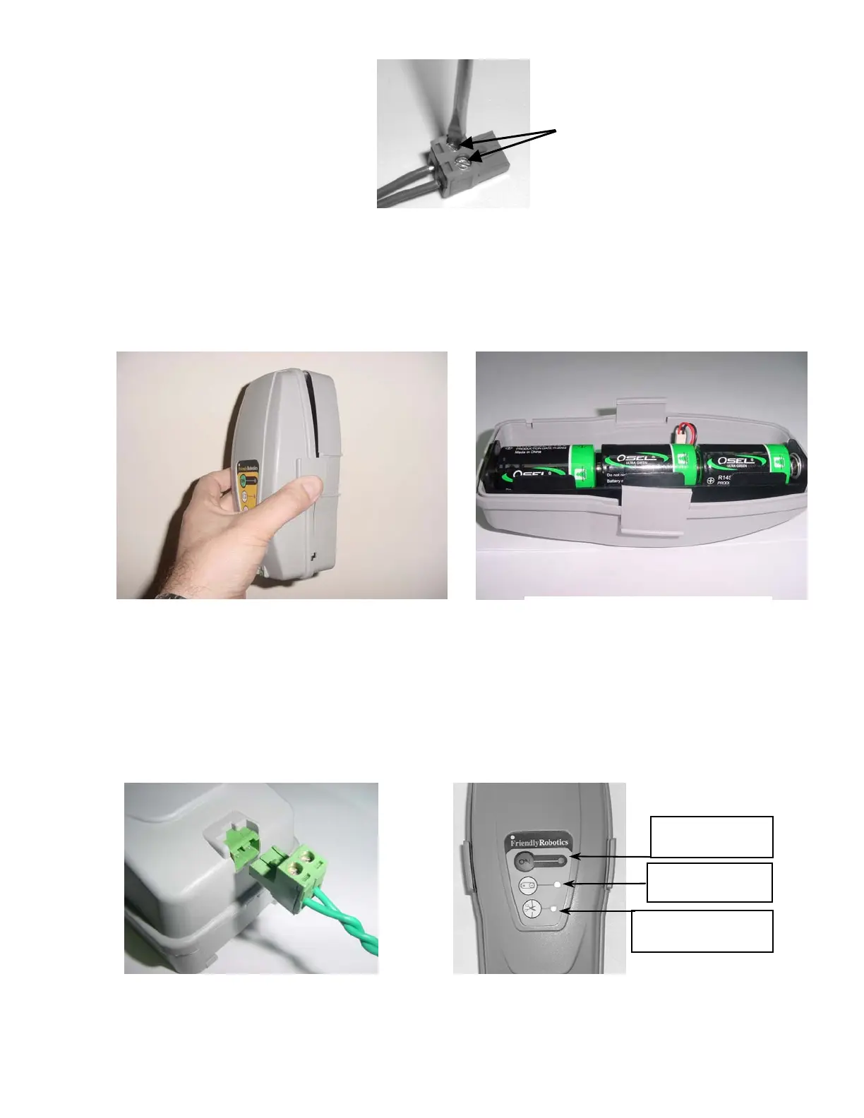
Take the Perimeter Switch and squeeze the tabs on both sides of the Perimeter Switch as shown in
figure 1.11, and remove the back cover from the Perimeter Switch.
Insert the 3 C-cell batteries in the battery holder as shown in Figure 1.12 and reassemble the Perimeter
Switch.
Figure 1.12 –
Inserting Batteries
Figure 1.11 -
Squeeze to remove cover
1.10 Test the Perimeter Switch
Plug the perimeter wire connector into the Perimeter Switch (see figure 1.13) and press the ON button.
A small flashing green light next to the ‘ON’ button indicates the system is on and functioning correctly.
The Perimeter Switch also has an indicator for low batteries and for a disconnected/broken perimeter
wire. Figure 1.14.
Figure 1.14 –
Perimeter Switch Operating Panel
ON button and
indicator li
ht
Low battery
indicator li
ht
Disconnected/broken
wire indicator light
Figure 1.13 –
Plug the plot connector into
the Perimeter Switch
19