Ed. 11/2006
User, Installation and Service Manual for F1 Gas Unit Heaters 20
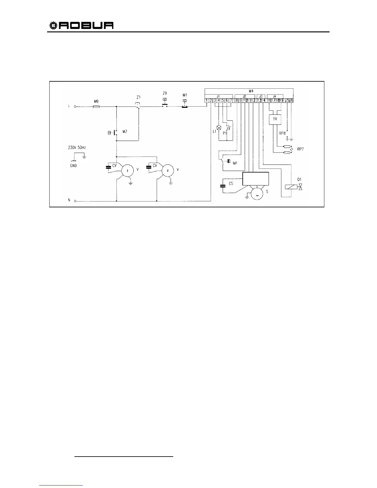
OPERATING WIRING DIAGRAM
Figure 18
LEGEND:
M9 fuse 5x20 6.3 A F NP pressure switch
M2 fan thermostat CS combustion blower capacitor (only for F1 21,31,41)
CV fan capacitor (2 pcs. for F1 61/81) S combustion blower motor
V fan motor ((2 pcs. for F1 61/81) TR ignition transformer
Z1 summer/winter switch RP7 ignition electrode
Z9 room thermostat RP8 flame sensor
M1 temperature limit thermostat Q1 gas valve
M4 flame control unit L El. Supply – phase
L1 lockout warning lamp N El. Supply – neutral
P1 reset button GND ground
BSRB Blower Speed regulation Board
BSRB