Heating engineer
Installation, use and maintenance manual – M gas unit heater
21
3
Table3.2 Permissible pressure drop depending on model and mounted diaphragm
Air diaphragm Fumes diaphragm Admissible pressure drop (Pa)
Height (mm) Code Height (mm) Code maximum Minimum
M20, M20 C ----- ----- 60 019 40 -----
M25
----- ----- ----- ----- 30 12
----- ----- 45 012 16 -----
M30, M30 C
84 007 ----- ----- 35 23
84 007 55 013 25 -----
M35, M36
----- ----- ----- ------ 42 25
----- ----- 40 014 24 10
----- ----- 50 020 12 -----
M40
----- ----- ----- ----- 30 19
----- ----- 35 026 19 -----
M50
----- ----- ----- ----- 27 8
----- ----- 35 026 8 -----
M60, M60 C
----- ----- ----- ----- 69 45
----- ----- 45 012 46 22
----- ----- 55 013 21 -----
Table3.3 Pressure drop for air and ue pipes and coaxial exhausts
M20 M20 C M25 M30 M30 C M35 M36 M40 M50 M60 M60 C
Flue gas exhaust pressure drop
Ø 110 mm
Pipe 1 m Pa 0,4 0,6 0,7 1,7 1,3 1,7 2,3 3,8
Elbow 90° Pa 0,7 1,3 1,4 3,7 2,8 3,7 5,1 8,6
Tee Pa 1,1 1,9 2,0 5,1 4,0 5,1 6,9 11,3
Ø 130 mm
Pipe 1 m Pa 0,2 0,3 0,8 0,6 0,8 1,0 1,7
Elbow 90° Pa 0,4 0,6 0,7 1,9 1,5 1,9 2,6 4,3
Tee Pa 0,5 0,8 0,9 2,3 1,8 2,3 3,1 5,0
Air intake pressure drop
Ø 130 mm
Pipe 1 m Pa 0,1 0,2 0,4 0,2 0,4 0,5 0,7
Elbow 90° Pa 0,2 0,3 0,4 0,9 0,5 0,9 1,2 1,8
Tee Pa 0,3 0,4 0,5 1,1 0,7 1,2 1,5 2,2
Coaxial exhaust pipe pressure drop
Ø 130/180
mm
wall (1) Pa 2,0 3,7 4,4 9,3 7,4 9,3 13,2 24,9
Ø 130/210
mm
roof Pa 2,2 4,3 4,9 10,6 8,2 10,6 14,5 29,4
(1) Can be used only with OSTF009 support bracket
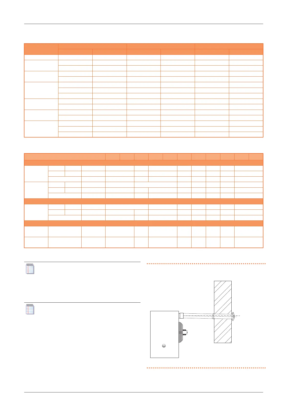
If horizontal ue gas exhaust pipes having lengths
above 1 m are installed, the ue gas exhaust pipe
must be mounted with a downward slope of 2 to 3
cm each 1-m length (Figure 3.7
p.21
), to prevent
condensate drops entering the unit.
In the case of installations of vertical ue pipes
longer than 1.5 m, to prevent any drops of con-
densation entering the generator, it is necessary
to provide a Tee element on the base of the ver-
tical ue pipe to collect any condensation (Figure
3.2
p.20
).
Figure3.7 Slope of horizontal pipes
For proper installation of the wall external terminals for
the ue gas exhaust and combustion air intake, follow the