Features and technical data
14
1
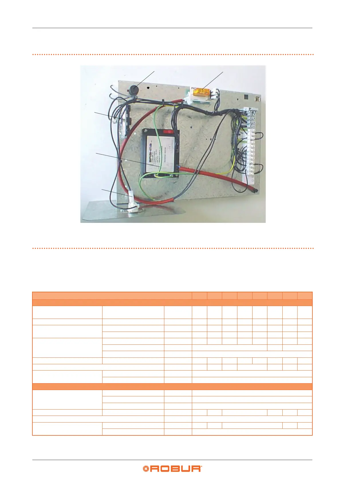
1.5 ELECTRICAL PANEL
Figure1.10 Electrical panel
A Internal components protection thermostat
B Limit thermostat
C Dierential pressure switch
D Controller for ignition, adjustment and ame control
E Pressure switch control relay
1.6 TECHNICAL DATA
Table1.2 Technical data
Axial fan models
M20 M25 M30 M35 M36 M40 M50 M60
Heating mode
Heat input
nominal (1013 mbar - 15 °C)
(1)
kW 20,6 28,8 34,8 42,2 39,4 48,2 57,3 72,5
Heat output nominal kW 18,3 25,5 30,7 37,4 34,9 42,5 50,7 63,8
Eciency
nominal heat input % 88,8 88,5 88,2 88,6 88,5 88,2 88,5 88,0
useful at 100% heat input % 88,5 88,2 87,9 88,3 88,2 87,8 88,0 87,5
Heat losses
to ue in operation % 11,20 11,50 11,80 11,40 11,50 11,80 11,50 12,00
to casing in operation % 0,30 0,40 0,50
with burner o % 0,25
Temperature rise nominal heat input K 20,5 29,4 23,8 28,6 26,6 27,8 29,8 27,3
lenght of throw (residual speed < 0,5 m/s) (2) m 12,0 15,0 18,0 20,0 21,0 23,0 25,0
Ambient air temperature (dry bulb)
maximum °C 35
minimum °C 0
Electrical specications
Power supply
voltage V 230
type - single-phase
frequency Hz 50
Electrical power absorption nominal kW 0,25 0,24 0,34 0,40 0,50 0,61
fuse A 4,0
Degree of protection
fan motor IP 42 44 54 44 54
appliance IP 20
(1) Relative to NCV (net caloric value).
(2) Values measured in an open area; in a real installation, the thermal ow may reach greater distances than those given here (depending on the height of the ceiling
and its thermal insulation).