16
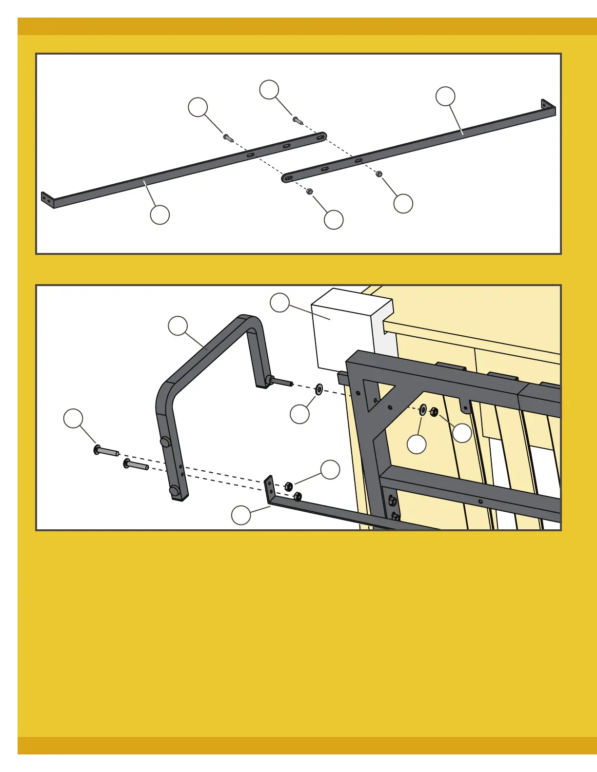
5. Connect the two sections of the Foot Bar (N) to form one
long bar with two M6 x 15mm Bolts (MM) and two M6
Nuts (OO). Make sure that the end plates of the two Foot
Bar sections are oriented the same way and that the nuts
will be on the inside of the Foot Bar when the bed is in the
open position and the Foot Bar is down. Fig. 14.
6. Pull the top of the bed frame out beyond the front of the
cabinet and install the Temporary Stops (GG) on the top
corners of the cabinet. Fig. 15.
7. With the Temporary Stops (GG) still holding the top of the
frame out from the cabinet, fit a Nylon Washer (DD) onto the
threaded stem of the left Leg (M) and fit the threaded stem
into its hole in the frame. Fit another Nylon Washer onto
the stem and secure with an M8 Locking Nut (FF). Do not
overtighten, or the leg might not pivot correctly. Fig. 15.
8. Repeat Step 7 for the right Leg (M).
9. Attach the assembled Foot Bar (N) to each of the Legs (M)
with two M6 x 30mm Bolts (AA) with two M6 Nuts (OO).
Secure with Allen Key #5 (S2). Fig. 15.
Fig. 15
Fig. 14
MM
MM
OO
OO
N
N
M
GG
DD
DD
FF
OO
N
AA


 To Next Page