Publication 520-PC001E-EN-P - September 2020 | Supersedes Publication 520-PC001D-EN-P - February 2016
Copyright © 2020 Rockwell Automation, Inc. All rights reserved. Printed in China.
Allen-Bradley, AppView, CustomView, expanding human possibility, FactoryTalk, PowerFlex, QuickView, Rockwell Automation, and TechConnect are trademarks of Rockwell Automation, Inc.
EtherNet/IP is a trademark of ODVA, Inc.
Trademarks not belonging to Rockwell Automation are property of their respective companies.
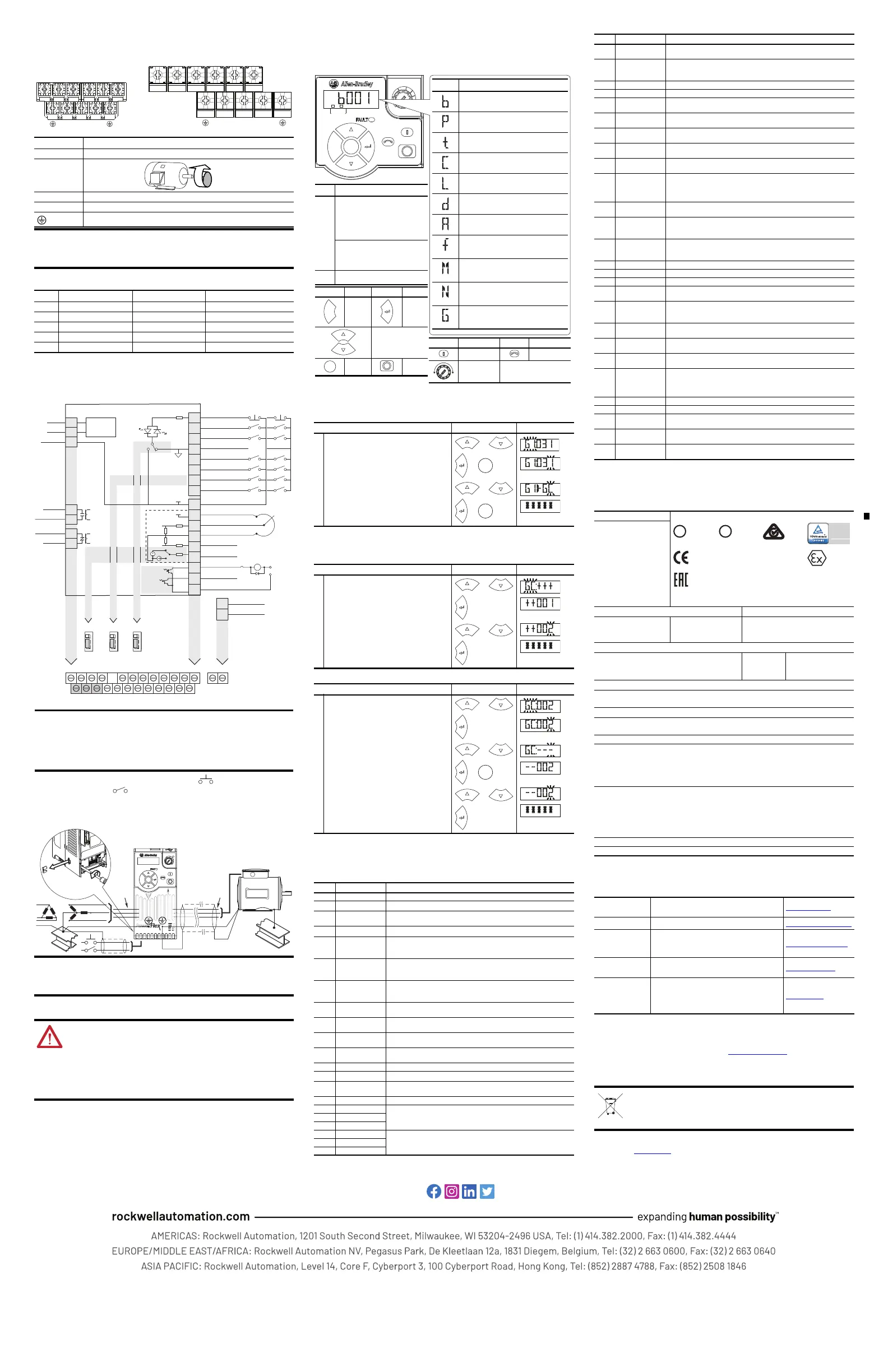
Power Terminal Block
Power Terminal Block Specifications
Control Terminal Block
General Grounding Requirements
Prepare For Drive Start-Up
LCD Display with QuickView Technology
QuickView® technology enables text to scroll across the LCD display of the PowerFlex 520-series
drive. This allows you to easily configure parameters, troubleshoot faults and view diagnostic
items without using a separate device.
AppView Parameter Groups
The parameters in the AppView® parameter groups can be quickly added to the CustomView™
parameter group by doing the following:
CustomView Parameter Group
You can copy one entire AppView parameter group to the CustomView parameter group as shown
above or add individual parameters as show below.
To delete parameters from the CustomView parameter group:
Fault Codes
To clear a fault – press the Stop key if P045 [Stop Mode] is set to a value between 0...3, cycle
power, set A551 [Fault Clear] to 1 or 2, or cycle digital input if t062, t063, t065...t068 [DigIn TermBlk
xx] is set to 13.
Specifications
Rockwell Automation Support
Use these resources to access support information.
Documentation Feedback
Your comments help us serve your documentation needs better. If you have any suggestions on
how to improve our content, complete the form at rok.auto/docfeedback
.
Waste Electrical and Electronic Equipment (WEEE)
Rockwell Automation maintains current product environmental compliance information on
its website at rok.auto/pec.
Terminal Description
L1/R, L2/S, L3/T Input Line Voltage Connection
T1/U, T2/V, T3/W Motor Phase
Connection
=
Switch any two motor leads to
change forward direction.
DC+, DC- DC Bus Connection
BR+, BR- Dynamic Brake Resistor Connection
Safety Ground – PE
Terminal screws may become loose during shipment. Ensure that all
terminal screws are tightened to the recommended torque before
applying power to the drive.
Frame Maximum Wire Size
(1)
(1)
Maximum/minimum sizes that the terminal block will accept – these are not recommendations.
Minimum Wire Size
(1)
Torq ue
A 5.3 mm
2
(10 AWG) 0.8 mm
2
(18 AWG) 1.76...2.16 Nm (15.6...19.1 lb-in.)
B 8.4 mm
2
(8 AWG) 2.1 mm
2
(14 AWG) 1.76...2.16 Nm (15.6...19.1 lb-in.)
C 8.4 mm
2
(8 AWG) 2.1 mm
2
(14 AWG) 1.76...2.16 Nm (15.6...19.1 lb-in.)
D 13.3 mm
2
(6 AWG) 5.3 mm
2
(10 AWG) 1.76...2.16 Nm (15.6...19.1 lb-in.)
E26.7 mm
2
(3 AWG) 8.4 mm
2
(8 AWG) 3.09...3.77 Nm (27.3...33.4 lb-in.)
The MOV to ground jumper must be removed if the drive is installed on
an ungrounded (IT mains) or resistive grounded distribution system.
Tighten screw after jumper removal.
ATTENTION: Power must be applied to the drive to perform the following start-up
procedures. Some of the voltages present are at incoming line potential. To avoid
electric shock hazard or damage to equipment, only qualified service personnel
should perform the following procedure. Thoroughly read and understand the
procedure before beginning. If an event does not occur while performing this
procedure, Do Not Proceed. Remove All Power including user supplied control
voltages. User supplied voltages may exist even when main AC power is not applied
to the drive. Correct the malfunction before continuing.
T2/VL3/TL2/SL1/R T1/U T3/W
T2/VL3/TL2/SL1/R T1/U T3/W
BR+
BR-
DC- DC+
BR+
BR-
DC-
DC+
Frame A, B, C and D Frame E
04
05
06
07
01
02
03
08
11
12
13
14
15
16
17
18
19
Digital Common
DigIn TermBlk 05
DigIn TermBlk 06
DigIn TermBlk 07/Pulse
Stop
(1)
DigIn TermBlk 02/
Start/Run FWD
(2)
DigIn TermBlk 03/
Direction/Run REV
DigIn TermBlk 08
R1
R2
S1
S2
S+
Relay 1 N.O.
Relay 1 Common
+24V DC
+10V DC
0-10V (or ±10V) Input
Analog Common
4-20mA Input
Analog Output
Opto Output 1
Opto Output 2
RJ45 Shield
Comm Common
Opto Common
+24V
+10V
Safety 1
Safety 2
Safety +24V
Typical
SNK wiring
Typical
SRC wiring
R1
S1 S2 S+ 11 12 13 14 15 16 17 18 19
R2 R5 R6 01 02 03 04 05 06 07 08 C1 C2
30V DC
50 mA
Non-inductive
Common
24V
(3)
Pot must be
1...10 k ohm
2 W min.
0-10V
0/4-20 mA
SNK
Digital In
DigIn TermBlk 07 Sel
Analog Out
Pulse In
SRCDigital
Input
0/4-20mA
0-10V
SRCSNK
R5
R6
Relay 2 Common
Relay 2 N.C.
C1
C2
Safe-Torque-O
Control I/O Wiring Block Diagram
I/O Terminal 01 is always a stop input. The stopping mode is
determined by the drive setting.
The drive is shipped with a jumper installed between I/O Terminals 01
and 11. Remove this jumper when using I/O Terminal 01 as a stop or
enable input.
(2) Two wire control shown. For three wire control use a momentary input on I/O Terminal 02 to command a
start. Use a maintained input for I/O Terminal 03 to change direction.
(3) When using an opto output with an inductive load such as a relay, install a recovery diode parallel to the relay as
shown, to prevent damage to the output.
U/T1
V/T2
W/T3
R/L1
S/L2
T/L3
SHLD
Esc
Sel
Step Key(s) Example Displays
1.
2.
3.
4.
Press the Up Arrow or Down Arrow to scroll to an
AppView group (G1...G8).
Press Enter or Sel to enter a group. The rightmost
digit of the last viewed parameter in that group will
flash.
Press the Up Arrow or Down Arrow to scroll to the
command G1->GC.
Press Enter or Sel to add all the parameters in this
AppView group to the CustomView group. The LCD
display will show a confirmation.
Step Key(s) Example Displays
1.
2.
3.
4.
Press the Up Arrow or Down Arrow to scroll to the
CustomView group (GC).
Press Enter to view the parameters that can be added
to the CustomView group.
Press the Up Arrow or Down Arrow to scroll through
the list of parameters.
Press Enter to add the parameter to the CustomView
group. The LCD display will show a confirmation.
Step Key(s) Example Displays
1.
2.
3.
4.
5.
6.
Press the Up Arrow or Down Arrow to scroll to the
CustomView group (GC).
Press Enter to view the parameters that are in the
CustomView group.
Press the Up Arrow or Down Arrow to scroll to the
command GC---.
Press Enter or Sel to view the parameters that are
stored in the CustomView group.
Press the Up Arrow or Down Arrow to scroll through
the list of parameters.
Press Enter to delete the parameter from the
CustomView group. The LCD display will show a
confirmation.
No. Fault Description
F000 No Fault –
F002
(1)
Auxiliary Input Check remote wiring. Verify communications programming for intentional fault.
F003 Power Loss Monitor the incoming AC line for low voltage or line power interruption. Check
input fuses. Reduce load.
F004
(1)
UnderVoltage Monitor the incoming AC line for low voltage or line power interruption.
F005
(1)
OverVoltage Monitor the AC line for high line voltage or transient conditions. Bus overvoltage
can also be caused by motor regeneration. Extend the decel time or install
dynamic brake resistor.
F006
(1)
Motor Stalled Increase P041, A442, A444 or A446 [Accel Time x] or reduce load so drive output
current does not exceed the current set by parameter A484 or A485 [Current
Limit x]. Check for overhauling load.
F007
(1)
Motor Overload An excessive motor load exists. Reduce load so drive output current does not
exceed the current set by parameter P033 [Motor OL Current]. Verify A530 [Boost
Select] setting.
F008
(1)
Heatsink OvrTmp Check for blocked or dirty heat sink fins. Verify that ambient temperature has
not exceeded the rated ambient temperature. Check fan.
F009
(1)
CC OvrTmp Check product ambient temperature. Check for airflow obstruction. Check for
dirt or debris. Check Fan.
F012 HW OverCurrent Check programming. Check for excess load, improper A531 [Boost Select]
setting, DC brake volts set too high or other causes of excess current.
F013
(2)
Ground Fault Check the motor and external wiring to the drive output terminals for a grounded
condition.
F015 Load Loss Verify connections between motor and load. Verify level and time requirements.
F021
(1)
Output Ph Loss Verify motor wiring and motor.
F029
(1)
Analog In Loss An analog input is configured to fault on a signal loss. A signal loss has occurred.
Check for broken/loose connections at inputs. Check parameters.
F033 Auto Rstrt Tries Correct the cause of the fault and manually clear.
F038 Phase U to Gnd Check the wiring between the drive and motor. Check motor for grounded phase.
Replace drive if fault cannot be cleared.
F039 Phase V to Gnd
F040 Phase W to Gnd
F041 Phase UV Short Check the motor and drive output terminal wiring for a shorted condition.
Replace drive if fault cannot be cleared.
F042 Phase UW Short
F043 Phase VW Short
F
W
D
ENET LINK
EtherNet/IP
➊
Menu Parameter Group & Description
Basic Display
Commonly viewed drive operating conditions.
Basic Program
Commonly used programmable functions.
Terminal Blocks
Programmable terminal functions.
Communications
Programmable communication functions.
Logic
Programmable logic functions.
Advanced Display
Advanced drive operating conditions.
Advanced Program
Remaining programmable functions.
Fault and Diagnostic
Consists of list of codes for specific fault
conditions.
Modified
Functions from the other groups with values
changed from default.
Network
Network functions that are shown only when
a comm card is used.
AppView and CustomView
Functions from the other groups organized
for specific applications.
No. Display/LED (Color)
➊
ENET (Steady) – Adapter connected to
network and drive controlled via
Ethernet.
ENET (Flashing) – Adapter connected
to network but drive not controlled via
Ethernet.
LINK (Steady) – Adapter connected to
network but not transmitting data.
LINK (Flashing) – Adapter connected to
network and transmitting data.
➋
Fault Status (Red)
Key Name Key Name
Escape Enter
Up Arrow
Down Arrow
Select Stop
➋
Key Name Key Name
Start Reverse
Potentiometer
F
W
D
F
W
D
F
W
D
F
W
D
F
W
D
F
W
D
PROGR
A
M
F
W
D
F048
(1)
Params Defaulted The drive was commanded to write default values to EEPROM. Clear the fault or
cycle power to the drive. Program the drive parameters as needed.
F059
(1)
Safety Open Both of the safety inputs (Safety 1, Safety 2) are not enabled. Check safety input
signals. If not using safety, verify and tighten jumper for I/O terminals S1, S2 and
S+.
F063
(1)
SW OverCurrent Verify connections between motor and load. Verify level and time requirements.
F064 Drive Overload Reduce load or extend Accel Time.
F070 Power Unit Check maximum ambient temperature has not been exceeded. Cycle power.
Replace drive if fault cannot be cleared.
F071 DSI Net Loss Cycle power. Check communications cabling. Check Modbus or DSI setting.
Check Modbus or DSI status.
F072 Opt Net Loss Cycle power. Check communications cabling. Check network adapter setting.
Check external network status.
F073 EN Net Loss Cycle power. Check communications cabling. Check EtherNet/IP™ setting. Check
external network status.
F080 Autotune Failure The autotune function was either cancelled by the user of failed. Restart
procedure.
F081 DSI Comm Loss Cycle power. Check communications cabling. Check Modbus or DSI setting.
Check Modbus or DSI status. Modify using C125 [Comm Loss Action]. Connecting
I/O terminals C1 and C2 to ground may improve noise immunity.
Replace wiring, Modbus master device or control module.
F082 Opt Comm Loss Cycle power. Reinstall option card in drive. Modify using C125 [Comm Loss
Action]. Replace wiring, port expander, option card or control module.
F083 EN Comm Loss Cycle power. Check EtherNet/IP setting. Check drive’s Ethernet settings and
diagnostic parameters. Modify using C125 [Comm Loss Action]. Replace wiring,
Ethernet switch or control module.
F091 Encoder Loss Check Wiring. If P047, P049 or P051 [Speed Referencex] = 16 “Positioning” and
A535 [Motor Fdbk Type] = 5 “Quad Check”, swap the Encoder channel inputs or
swap any two motor leads. Replace encoder.
F094 Function Loss Close input to the terminal and cycle power.
F100 Parameter Chksum Set P053 [Reset to Defalts] to 2 “Factory Rset”.
F101 External Storage Set P053 [Reset to Defalts] to 2 “Factory Rset”.
F105 C Connect Err Clear fault and verify all parameter settings. Do not remove or install the control
module while power is applied.
F106 Incompat C-P The control module could not recognize the power module. Cycle power. Flash
with newer firmware version.
Replace drive if fault cannot be cleared.
F107 Replaced C-P The control module was mounted to a power module with a different power
rating. Set P053 [Reset to Defalts] to any of the reset options.
F109 Mismatch C-P The control module was mounted to a different drive type power module. Set
P053 [Reset to Defalts] to any of the reset options.
F110 Keypad Membrane Keypad membrane failure/disconnected. Cycle power.
Replace control module if fault cannot be cleared.
F111 Safety Hardware Safety input enable hardware malfunction. One of the safety inputs is not
enabled. Check safety input signals. If not using safety, verify and tighten jumper
for I/O terminals S1, S2 and S+.
Replace control module if fault cannot be cleared.
F114 uC Failure Cycle power. Replace control module if fault cannot be cleared.
F122 I/O Board Fail Cycle power. Replace drive or control module if fault cannot be cleared.
F125 Flash Update Req Perform a firmware flash update operation to attempt to load a valid set of
firmware.
F126 NonRecoverablErr Clear fault or cycle power to the drive. Replace drive or control module if fault
cannot be cleared.
F127 DSIFlashUpdatReq Perform a firmware flash update operation using DSI communications to
attempt to load a valid set of firmware.
(1)
This fault may be cleared by the auto-restart routine and will be attempted a number of times based on the value set
in parameter A541 [Auto Rstrt Tries].
(2)
This fault may be cleared by the auto-restart routine and will be attempted only once. It ignores the value set in
parameter A541 [Auto Rstrt Tries].
Input/Output Ratings Approvals
Output Frequency:
0...500 Hz
(Programmable)
Efficiency:
97.5% (Typical)
Digital Control Inputs (Input Current = 6 mA) Analog Control Inputs
SRC (Source) Mode:
18...24V = ON
0...6V = OFF
SNK (Sink) Mode:
0...6V = ON
18...24V = OFF
4-20 mA Analog: 250 input impedance
0-10V DC Analog: 100 k input impedance
External Pot: 1...10 k, 2 W min.
Control Output
Programmable Output, Form A and Form B
Resistive Rating: 3.0 A @ 30V DC, 125V AC and 240V AC
Inductive Rating: 0.5 A @ 30V DC, 125V AC and 240V AC
Opto Outputs
30V DC, 50 mA
Non-inductive
Analog Outputs (10-bit)
0-10V: 1 k min.
4-20 mA: 525 max.
Fuses and Circuit Breakers
Recommended Fuse Type: UL Class J, T or Type BS88; 600V (550V) or equivalent.
Recommended Circuit Breakers: HMCP or equivalent.
Protective Features
Motor Protection:
I
2
t overload protection – 150% for 60 s, 200% for 3 s (Provides Class 10 protection)
Overcurrent: 200% hardware limit, 300% instantaneous fault
Over Voltage:
100...120V AC Input – Trip occurs @ 405V DC bus voltage (equivalent to 150V AC incoming line)
200...240V AC Input – Trip occurs @ 405V DC bus voltage (equivalent to 290V AC incoming line)
380...480V AC Input – Trip occurs @ 810V DC bus voltage (equivalent to 575V AC incoming line)
525...600V AC Input – Trip occurs @ 1005V DC bus voltage (equivalent to 711V AC incoming line)
Under Voltage:
100...120V AC Input – Trip occurs @ 190V DC bus voltage (equivalent to 75V AC incoming line)
200...240V AC Input – Trip occurs @ 190V DC bus voltage (equivalent to 150V AC incoming line)
380...480V AC Input – Trip occurs @ 390V DC bus voltage (equivalent to 275V AC incoming line)
525...600V AC Input – If P038 = 3 “600V” trip occurs @ 487V DC bus voltage (344V AC incoming line);
– If P038 = 2 “480V” trip occurs @ 390V DC bus voltage (275V AC incoming line)
Control Ride Through: Minimum ride through is 0.5 s - typical value 2 s
Faultless Power Ride Through: 100 ms
Technical Support
Center
Find help with how-to videos, FAQs, chat, user
forums, and product notification updates.
rok.auto/support
Knowledgebase Access Knowledgebase articles. rok.auto/knowledgebase
Local Technical
Support Phone
Numbers
Locate the telephone number for your country. rok.auto/phonesupport
Literature Library
Find installation instructions, manuals,
brochures, and technical data publications.
rok.auto/literature
Product
Compatibility and
Download Center
(PCDC)
Download firmware, associated files (such as
AOP, EDS, and DTM), and access product release
notes.
rok.auto/pcdc
At the end of life, this equipment should be collected separately from
any unsorted municipal waste.
No. Fault Description
U
L
®
L
I
S
T
E
D
9
6
6
X
I
N
D
C
O
N
T
E
Q
UL508C
U
L
®
L
I
S
T
E
D
9
6
6
X
I
N
D
C
O
N
T
E
Q
C
CSA 22.2
LV Directive 2014/35/EU: EN 61800-5-1
EMC Directive 2014/30/EU: EN 61800-3
Machine Directive 2006/42/EC: EN 60261
ATEX Directive 2014/34/EU: EN 50495
RoHS Directive 2011/65/EU
N223
AC 156
KCC: Article 58-2 of Radio Waves Act, Clause 3
Lloyds Register: Approval Certificate 12/10068(E1)
SEMI F47
Low Voltage TP TC 004/2011
EMC TP TC 020/2011
II (2) G D
Functional
Safety
Type
Approved
www.tuv.com
ID 0600000000
 Loading...