EasyManua.ls Logo

Rodix FEEDER CUBE VF-3-OF - User Manual

Rodix FEEDER CUBE VF-3-OF
10 pages
Print Icon
To Next Page IconTo Next Page
Loading...
File No. E183233
RODIX INCORPORATED
TOLL FREE (800) 562-1868, FAX (815) 316-4701
E-mail custserve@rodix.com
rodix.com
FEEDER CUBE ®
VF-3-OF, P/N 121-000-0777* and 121-200-0777
* Includes CFR vibration sensor P/N 123-215
OPEN FRAME MODEL
IMPORTANT: APPLICATION NOTE
Input: 85 - 264 VAC, 50/60 HZ.
Single Unit Fuse Size: 5 AMPS
Output: 0 - 120/240 VAC
Maximum output voltage matches input voltage
Output Frequency: 5 - 180Hz
Rated Output Current: 3 Amps at 120V or 2 Amps at 240V
Model Information: The Autotune Series of Variable Frequency Feeder Cubes® generates an output frequency for feeding
that is independent from the power line frequency. An optional vibration sensor, P/N 123-215, can be used to maintain the
vibratory feeder at a constant feed rate. The start/stop operation of the output can be controlled with an optional parts
sensor. For more information on this control, refer to the enclosed Adjustments and Set Up pages.
Mount Open Frame controls within an enclosure. Mount the fuse holders external to the control with #8 screws. For single
phase 120 or 240 VAC installations, install a “Hot” wire fuse, don’t fuse the neutral wire. Use only the Littlefuse 3AB “Fast
Acting” type of fuse. The customer supplied power switch wires to the fuse(s). Disconnect the power before making
electrical connections to the terminal block plugs. The customer supplied power switch should be rated 10 amps, 240V or
more.
© 2012, 2020 RODIX
INC
. 11/20/20 Page 1
Question and Answer IconNeed help?

Do you have a question about the Rodix FEEDER CUBE VF-3-OF and is the answer not in the manual?

Summary

Application Note

Product Specifications

Lists key electrical and operational parameters for the feeder control.

Model Information

General Description

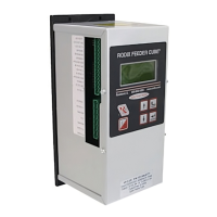
Provides an overview of the Autotune Series Feeder Cubes.

Wiring Diagram

VF Series Master Control Wiring

Illustrates connections for the master VF Series control unit.

VF Series Subordinate Control Wiring

Shows wiring for a subordinate VF Series control unit.

Control Menu Layout

Power and Frequency Settings

Adjusts amplitude, soft start, frequency, and auto scan.

I;O and Timer Settings

Configures sensor polarity, run mode, and delays.

Diagnostics and Security

Accesses system info, error messages, and security settings.

Normal Display Message Priority

Message Priority Logic

Lists display messages by priority from highest to lowest.

Electrical Connections

Sensor and Input Connections

Covers parts sensor input and run input enable configurations.

Output and Power Connections

Details auxiliary output and main power connection instructions.

Internal Power Supply Details

Details the 24 VDC internal power supply capabilities.

Software Adjustments

Navigating the Control Menu

Explains how to use the keypad to navigate program menus.

Amplitude Settings

Covers max, min, and soft-start settings for output amplitude.

External Speed & Frequency Control

Details controlling speed and frequency via external signals.

Control Settings and Configuration

Frequency and Tuning

Adjusts output frequency, auto scan, and auto tracking parameters.

Input and Timer Settings

Configures parts sensor, run mode, and time delays.

System Configuration, Diagnostics, and Support

Diagnostics, Defaults, and CFR Settings

Accesses system info, errors, saves, and CFR set point.

Security and Language Options

Manages access codes, keypad lock, and display language.

Warranty and Support Information

Outlines product warranty and contact details.

Interlocking VF Series Controls

VF to VF Interconnection

Details wiring for master/subordinate VF Series control interlocking.

VF to FC-40 Plus Interconnection

Describes wiring to interlock VF Series with FC-40 Plus.

VF to FC-200 Interconnection

Explains wiring for interlocking VF Series with FC-200.

Installing the CFR Sensor

Sensor Mounting and Wiring

Guides sensor placement, surface prep, and connection to control.

Software Configuration and Scan

Sets up control menu for CFR and performs auto scan.

Rodix Solution: Electrical Noise

Symptoms of Electrical Noise

Describes typical signs of electrical noise interference.

Sources of Electrical Noise

Identifies common devices that generate electrical noise.

Noise Reduction Solutions

Provides guidelines for using shielded wires, conduits, and snubbers.

Rodix FEEDER CUBE VF-3-OF Specifications

General IconGeneral
ModelVF-3-OF
Protection ClassIP20
TypeFeeder
Output Current3A
Operating Temperature0°C to 40°C