EN
62
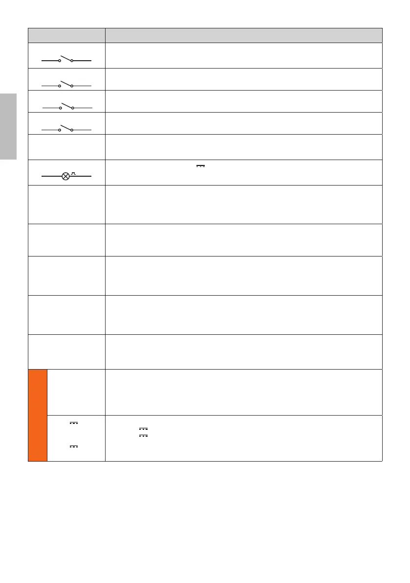
CONTACT DESCRIPTION
23(AP) 21(COM)
Open control signal input (N.O.).
IMPORTANT: persistent activation of the opening command prevents automatic reclosure; the automa-
tic reclosure time count is resumed when the opening command is released.
24(CH) 21(COM)
Close command input (N.O.).
25(PP) 21(COM)
Step by step mode command input (N.O.).
The function of the control is determined by parameter $.
26(PED) 21(COM)
Partial open control signal input (N.O.).
Set by default to 50% of completely open position.
27(+24V) 28(COM)
Power feed for external devices. See technical characteristics.
Connecting B72/BRAKE - B72/BRCL power unit for BH30 -NLM8UJJIܪLBH30 Reversible ܪL
and BM30-NLM8UJJI[JWXNTSXܪL
29(LAM) 28(COM)
(TSSJHYNTSKTWܫFXMNSLQNLMY (24V - duty cycle 50%).
9MJXJYYNSLXKTWYMJUWJRFSTJZ[WJܫFXMNSL\FWSNSLXNLSFQRF^GJXJQJHYJI\NYMUFWFRJYJW$, while
YMJܫFXMNSLRTIJNXXJY\NYMUFWFRJYJW.
ENC
Connector for connecting to encoder installed on motor.
WARNING! Always disconnect from electrical power before disconnecting or connecting the encoder
cable.
In case of encoder replacement, repeat the acquisition procedure.
N.B.: Ready wired in factory by ROGER TECHNOLOGY.
FC
Connector (N.C. contacts) for connecting mechanical limit switch (see ܪLZWJ - detail E) or magnetic
limit switch (see ܪLZWJ - detail F). The gate stops when the limit switch is activated. IMPORTANT:
repeat the travel acquisition procedure after each adjustment to the limit switches.
N.B.: Ready wired in factory by ROGER TECHNOLOGY.
SB
Connector (N.C.) for connecting release contact. If the motor release handle is opened, the gate stops
and no command signals are accepted.
Once the release handle is closed again, if the gate is in an intermediate position, the controller unit
initiates the position recovery procedure (see chapter 18).
N.B.: Ready wired in factory by ROGER TECHNOLOGY.
RECEIVER CARD
Connector for plug-in radio receiver board.
The control unit has two radio remote control functions by default:
– 57XYJURTIJHTRRFSIRTINܪFGQJ\NYMUFWFRJYJW).
– 57UFWYNFQTUJSNSLHTRRFSIRTINܪFGQJ\NYMUFWFRJYJW).
The programming buttons PR1 and PR2FWJFQXTFHHJXXNGQJ\NYMYMJHT[JWHQTXJIXJJܪL
WIFI
Connector for B74/BCONNECT WiFi IP device.
This IP device allows, using any internet browser, the complete management of the control panel both in
proximity (point-to-point connection) and via cloud (remote connection).
ONLY BH30 Series
BATTERY
CHARGER
B71/BC
In the event of a mains power loss, the controller unit is powered by the batteries. When battery power
is used, E$WWNXXMT\STSYMJINXUQF^FSIYMJܫFXMNSLQNLMYܫFXMJXGWNJܫ^FYNSYJW[FQXZSYNQRFNSXUT\JW
is restored or until the battery voltage drops below the minimum permissible limit. In this case, EW/2
(Battery Low) is shown on the display and the controller unit accepts no commands.
WARNING! the batteries must always be connected to the electronic controller unit in order to charge.
Periodically (at least every 6 months), check that the battery is in good working order.
2x12V
1,2 Ah.
or
2x12V
4,5 Ah
Two battery kits are available:
• Two 12V 1.2 Ah batteries installed in the automation system itself.
• Two 12V , 4.5 Ah batteries installed in an external case.
For more information, refer to the installation manual for the B71/BC battery charger.
WARNING: it is recommended to use AGM type batteries.
 Loading...