EN
83
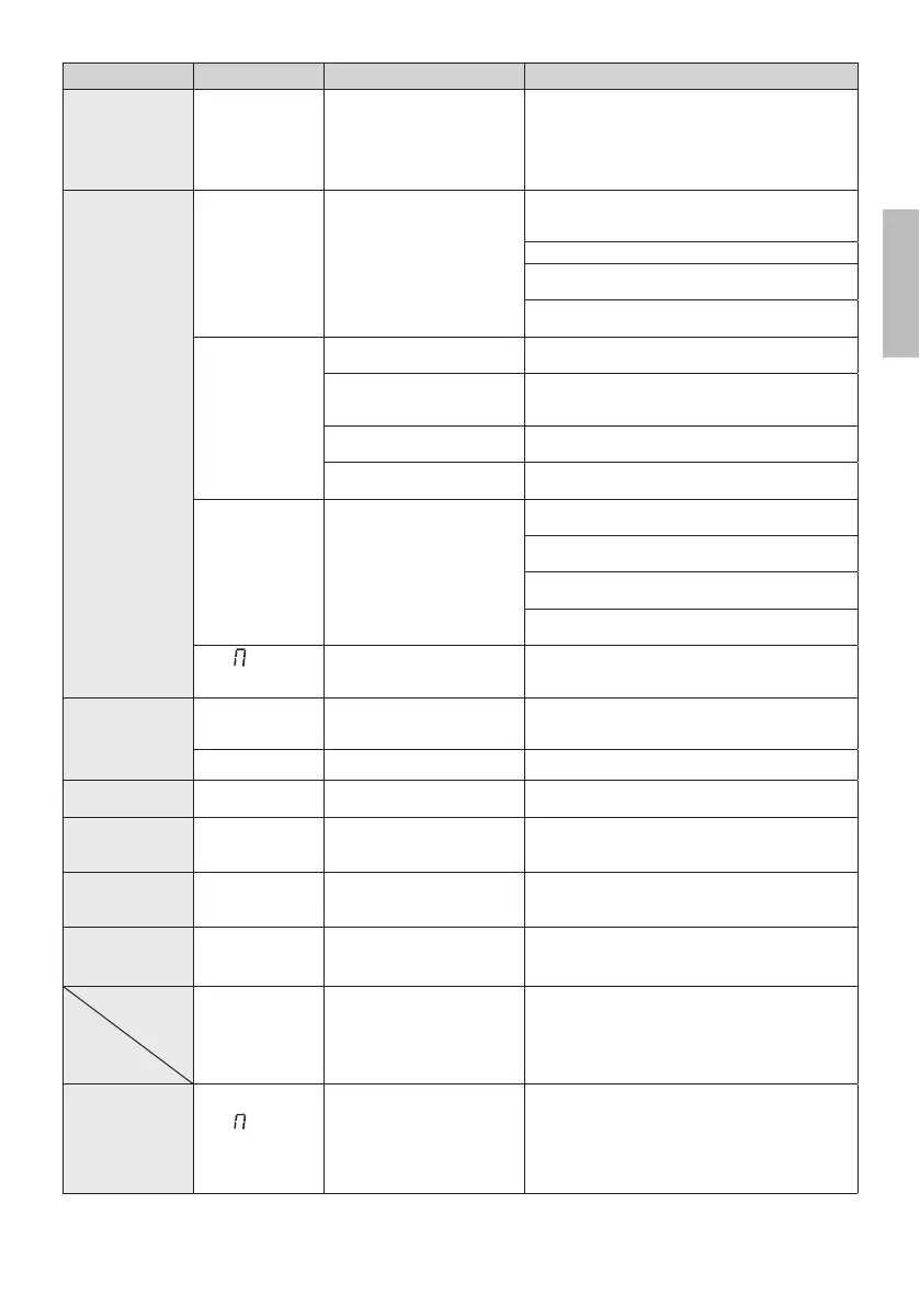
PROBLEM ALARM POSSIBLE CAUSE ACTION
The gate does not
open or close.
QR 3+
Problems at the encoder circuit
or at the connection cable.
Check the integrity of the connection cable.
Disconnect and reconnect the power supply.
Give a command (opening / step-by-step, ...).
If QR3+ is NOT displayed, repeat the acquisition procedure.
If QR3+ is displayed again, contact the technical ser-
vice department.
Acquisition
procedure does
not complete
correctly.
QR 3+
Motor calibration failed. Repeat acquisition procedure.
If the problem persists, check the cable connecting the
encoder to the motor.
Check if release handle is open.
Check that the motor turns without impediment. Con-
tact technical support in case of any problems.
Check that the mains voltage is correct and that the
mains cable cross-section is adequate.
$3 3(
TEST button pressed acciden-
tally.
Repeat acquisition procedure.
Safety devices in alarm state. Press the TEST button and check the safety device/s
in alarm state and the connections of the safety de-
vices.
Excessive voltage drop. Repeat acquisition procedure.
Check mains voltage.
Incorrect setting of parameters
and .
Adjust parameters and correctly for the weight
and speed of the gate leaf.
DS S/
Travel length error.
Move gate into completely closed position (FC limit
switch signal must be active) and repeat the procedure.
Check cable of limit switches. Replace the cable if the
problem persists.
Reset default controller unit parameters and repeat the
procedure.
Stroke length less than the minimum allowed: increase
the length.
DSS
Maximum permitted travel
length exceeded
Reduce the ride. Contact technical assistance (travel
exceeding the maximum allowed by the technical cha-
racteristics).
Remote control
has limited range
and does not work
while automated
gate is moving.
The radio transmission is im-
peded by metal structures and
reinforced concrete walls.
Install the antenna outside.
Flat batteries. Replace the transmitter batteries.
9MJܫFXMNSLQNLMY
is not working.
'ZQG 1*) GQT\S TW ܫFXMNSL
light wires disconnected.
Check LED circuit and/or connector wires.
Gate open
indicator lamp
does not work.
Bulb blown or wires discon-
nected.
Check the bulb and/or wires.
Gate does not
perform desired
manoeuvre.
Incorrect setting of parameter
.
Select the correct installation position with parameter
.
The control unit is
switched off and
does not start.
F2 fuse blown due to overvol-
tage.
Replace the 2A F2 fuse.
6(/)
Only for BH30/804/R. The gate
is moved by hand without being
unlocked, without mains and/or
battery voltage
WARNING: if B71/BC is used, check the correct con-
nection of the battery charger to the control unit (the
red cable [+] must be connected to the POWER IN ter-
minal 5, the black cable [-] must be connected to the
POWER IN terminal 4). Otherwise, the manual mano-
euvre will not be performed correctly.
The control unit
does not accept
commands.
6(/)
$/,
Incorrect connection of the
battery charger to the control
unit. After 5 s the display shows
&1.2 YT HTSܪWR YMJ NSHTWWJHY
connection of the POWER-IN
terminal strip.
Reverse the connection of the (+) and (-) wires on the
POWER IN terminal strip of the control unit (see batte-
ry connection at page 2)
By pressing the TEST button, the error can be tempora-
rily hidden to consult the control unit parameters.
N.B.: Press the TEST button to temporarily cancel the alarm.
The next time a command is received, the alarm reappears on the display if the problem has not been resolved.
 Loading...