PRT-LT Series Readers fv1.25 Rev. G 2016-10-08
Page 9 from 17
3.3. INSTALLATION GUIDELINES
· Reader should be installed in such a way to assure physical access to the connection cable
· A new factory delivered unit is configured for RACS address ID=0 however data output
format can be changed whenever required using Memory Reset procedure
· The PRT-LT reader should be mounted near the supervised door on a vertical piece of
supporting structure
· Disconnect power supply before making any electrical connections
· Be aware that when installing the reader directly on the metal type surface card reading
distance will deteriorate
· For installations on a metal surface you can place a non-metallic 10 mm thick spacer (a
plastic/plaster plate etc.) between the reader and the supporting structure
· For installations with two readers to be mounted on the opposite sides of the same wall and
aligned along the same geometrical axis, place a metal plate between them and make sure
none of two readers has direct contact with it (allow min. 10 mm space)
· For best results mount the proximity readers at least 0.5 m apart
· With its relatively weak electromagnetic field generation, reader should not cause any
harmful interference to operation of other equipment. However, its card reading
performance can be affected by other interference generating devices, esp. radio waves
emitting equipment or CRT computer monitors
· If card reading performance of the reader deteriorates (e.g. reduced reading range or
incorrect readings) consider reinstallation in a new location.
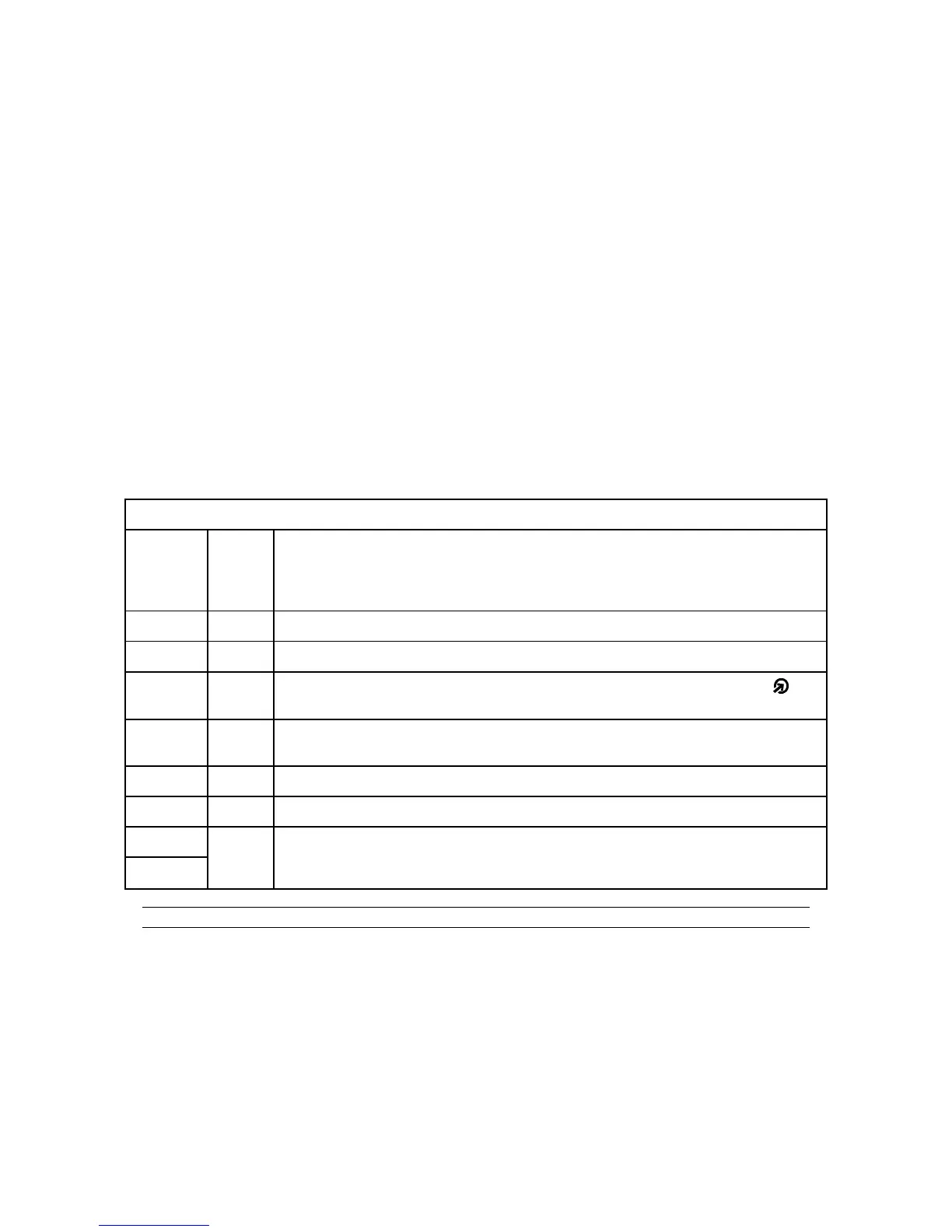
Connection terminal assignments
Wire
Color
Label Function
Green CLK DATA 0 line for Wiegand, CLOCK for Magstripe and RACS
Brown DTA DATA 1 line for Wiegand, DATA for Magstripe and RACS
Yellow IN1
Input line; in Wiegand and Magstripe formats this line controls LED OPEN .
Line is active when shorted to ground
Pink IN2 Input line; in Wiegand and Magstripe formats this line controls internal sunder
of the reader. Line is active when shorted to ground
Red +12V Supply input plus
Blue GND Supply input minus
Grey TAMP Tamper switch contacts, normally closed, isolated, IP67, 24V/50mA. Contact
became open when unit is detached from the place of installation or upper part
of enclosure is open
White
Note: For screw terminals assignments see additional drawings later in this document.
 Loading...