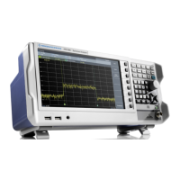
Instrument Tour
R&S
®
FPL1000
43Getting Started 1323.1602.02 ─ 07
For safety information concerning batteries, see "Handling batteries safely"
on page 10.
As an alternative, a DC power supply connector (option R&S FPL1-B30) is availa-
ble. DC power supplies from +12 V to +24 V and from 13 A to 6.5 A can be used.
Connect the connector according to the following diagram:
Pin Description
1 2
3
1 Plus
2 Ground
3 Not used
If you use an external power supply unit to supply safety extra-low DC voltage
(SELV) to the instrument, be sure to meet the requirements for reinforced/double
insulation in accordance with DIN/EN/IEC 61010 (UL 3111, CSA C22.2 No.
1010.1) or DIN/EN/IEC 60950 (UL 1950, CSA C22.2 No. 950). Provide current
limitation in accordance with DIN EN 61010-1 Appendix F2.1.
Also see "Connecting to power" on page 8.
5.2.2 AC Power Supply Connection and Main Power Switch
An AC power supply connector and main power switch are located in a unit on
the rear panel of the instrument.
Main power switch function:
Position 1: The instrument is in operation.
Position O: The entire instrument is disconnected from the AC power supply.
For details, refer to "Connecting to power" on page 8 and Chapter 4.5, "Connect-
ing to Power", on page 21.
5.2.3 GPIB Interface
The optional GPIB interface (R&S FPL1-B10) is in compliance with IEEE488 and
SCPI. A computer for remote control can be connected via this interface. To set
up the connection, a shielded cable is recommended.
Rear Panel View

 Loading...


