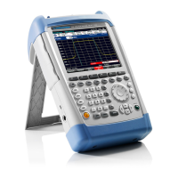
R&S FSH Performance Test
1145.5973.82 1.9 E-11
Checking the display linearity
Test equipment: - Signal generator (refer to section "Measurement Equipment and
Accessories", item 1)
- Power meter (refer to section "Measurement Equipment and
Accessories", item 3)
- Power sensor (refer to section "Measurement Equipment and
Accessories", item 4)
- 6-dB power splitter (refer to section "Measurement Equipment and
Accessories", item 2)
Test setup: Connect the power sensor (item 4) to the power meter and execute
function ´ZERO´ when there is no signal applied to the power sensor.
Connect the RF output of the signal generator to the input of the
divider.
Connect output 1 of the divider to the power sensor / power meter.
Connect output 2 of the divider to the RF input of the R&S FSH.
1
st
Measurement
0 to 30 dB below reference level
Signal generator settings: - Frequency 100 MHz
- Level + 6 dBm
Determine the output power of the signal generator with the power
meter. Adjust the output power of the generator until the power meter
shows
0 dBm.
R&S FSH settings:
- [ PRESET ]
- [ AMPT: 0 dBm ]
- [ FREQ: 100 MHz ]
- [ SPAN : 10 kHz ]
- [ Manual Res BW : 1 kHz ]
- [ Manual SWPTime : 1 s ]
- [ TRACE : DETECTOR : RMS ]
Reference measurement: Set the marker to the peak of the signal.
- [MARKER: SET MARKER: PEAK ]
The signal level L
is displayed by the level reading of the marker.
Ref
0dBm
= L - L
powermeter
Signal generator settings: - Frequency 100 MHz
- Level Sig_Lev + 6 dB
Refer to table under “Performance Test Report” for values of {Sig_Lev}.
Determine the output power of the signal generator with the power
meter. Adjust the output power of the generator until the power meter
shows the value of {Sig_Lev}.

 Loading...


