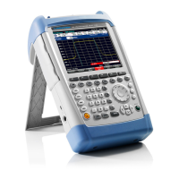
R&S FSH Instrument Design and Functional Description
1145.5973.82 3.5 E-11
Processing of measured data detectors
The measured data is processed in two dedicated ICs to reduce the sample rate of the input signal to a
value that can be handled by the hardware. The DDC converts the digital IF signal to I/Q base band and
filters the base band signals using low pass filters with programmable bandwidth. In addtiotion it delivers
the AM or FM demodulated audio signal. The DCON Asic detects the envelope of the filtered and
combined base band signal and calculates its logarithm. It contains also the video filter and the different
detectors. In addition it is resposible for the sweep control of the FSH.
DDC
DCON
Detectors
Filters
Counter
Control
RAM
AM
DAC
FM
DAC
Audio
Amp
Address, DATA and control bus
12
Measurement
data
T
RIGGER
A
F OUT
Fig. 3-3 Measured Data Processing
Resolution bandwidths (RBW)
The resolution bandwidths are implemented in the R&S FSH through digital processing in the DDC
ASIC (Digital Down Converter). The RBW can be selected from within the range 1 kHz to 1 MHz in 1-, 3-
or 10-unit increments. The DDC first mixes its input IF to the baseband using an NCO (Numeric
Controlled Oscillator) and then filters the resulting IQ signals via a combination of HDF (High Decimation
Filter) and an FIR (Finite Impulse Response) stages. At the end of the DDC processing chain, the IQ
signal is split into magnitude and phase.
For AF demodulation the amplitude information is used. In the case of FM the phase information is used
and fed to the headphone connector. In the analyzer mode the signal at the position of the marker can
be demodulated. In this case the R&S FSH stops the sweep for a selectable period of time and
demodulates the input signal. The volume can be adjusted.
For a standard log display of the analyzed spectrum, the magnitude data is converted from linear to
logarithmic in the DCON ASIC (Digital CONtroller).
Video bandwidths (VBW)
The video filters can be adjusted between 10 Hz and 3 MHz in increments of 1/3/10. They are designed
as digital lowpass filters for the video signals in the DCON ASIC. Software can couple the VBW to the
RBW, or the VBW can be set independently.

 Loading...


