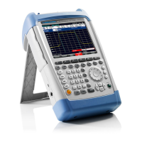
Module Replacement R&S FSH
1145.5973.82 3.10 E-11
Opening the instrument
(See exploded drawing for related numbers.)
Disconnect the power plug.
Switch the instrument to OFF.
Loosen the six (S1) screws and remove the top cover (2.4) and bottom cover (2.1).
Disconnect the connector (X2).
Loosen the three (S2) screws and remove the grip cover (2.3).
Loosen the two (S3) screws and remove the rear case (2.2).
Loosen the nine (S4) screws and remove the mainboard shielding.
Closing the instrument
Mount the mainboard shielding and fasten the nine (S4) screws.
Note that the shielding of wire-tree (W1) is reconnected again.
Mount the rear case (2.2) and fasten the two (S3) screws.
Mount the grip cover and fasten the three (S2) screws.
Connect the connector (X2).
Mount the top cover (2.4) and bottom cover (2.1).
Fasten the six (S1) screws .
Perform the quick verification test.
Refer to Chapter 2 “Adjustment”.
Caution! Note that the connecting cables are still connected.
Note: When detaching the connectors, proceed with caution.
Fig. 3-5 Opening the instrument

 Loading...


