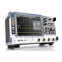
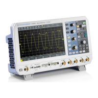
The R&S®RTB2000 Oscilloscope is a versatile instrument designed for measurements on circuits that are indirectly connected to the mains or not connected at all, making it suitable for industrial, administrative, and laboratory environments. It is not rated for any measurement category. The device is intended for the development, production, and verification of electronic components and devices.
Function Description
The R&S®RTB2000 oscilloscope offers a wide range of functions for waveform display, analysis, and signal generation. Its touchscreen display provides an intuitive interface, similar to a mobile phone, allowing users to access functionality through a main menu, shortcuts, and gestures.
Waveform Setup:
The oscilloscope allows users to connect various probe types, including passive and active voltage probes, and current probes. It automatically recognizes Rohde & Schwarz probes and displays their characteristics. Users can manually set measurement units and attenuation for unrecognized probes. The [Autoset] function analyzes enabled analog channel signals and adjusts horizontal, vertical, and trigger settings for stable waveforms. The [Preset] function resets the instrument to default scope mode, disabling all channels and waveforms except channel 1.
Horizontal Setup:
Horizontal settings, or timebase settings, adjust waveforms horizontally. Key parameters include:
- Horizontal Position: Defines the time distance of the trigger point to the reference point, allowing analysis before or after the trigger.
- Reference Point: The rescaling center of the time scale.
- Time Scale: Defines the horizontal axis time scale for all signals.
- Zoom: Magnifies a part of the waveform for detailed viewing, available in horizontal and vertical modes.
Vertical Setup:
Vertical settings control the vertical scale, position, and display of waveforms. Each analog channel has a dedicated key for activation and menu access. Key settings include:
- Offset/Position: Adjusts the offset or position of analog, math, or reference waveforms.
- Scale: Sets the vertical scale in Volts per division.
- Coupling: Selects input coupling (AC or DC) and termination. AC coupling blocks DC components, while DC coupling passes all signal components.
- Bandwidth: Selects bandwidth limits to reduce noise.
- Invert: Inverts the signal amplitude display.
- Deskew: Compensates for delay differences between channels.
- Zero Adjust: Corrects zero errors caused by differences in DUT and oscilloscope ground levels.
- Waveform Color: Selects color scales (Temperature, Rainbow, Fire, Default) for waveform display.
- Threshold: Used for digitization of analog signals, defining high/low states.
- Hysteresis: Avoids signal state changes due to noise.
- Label: Defines a name label for the selected waveform.
Acquisition Setup:
The R&S®RTB2000 captures signals and converts them to digital samples, which are then processed according to acquisition settings.
- Record Length: Sets the number of waveform samples stored in a record.
- Acquire Mode: Defines how waveforms are built from captured samples, including "Sample," "Peak Detect," "High Resolution," "Average," and "Envelope."
- Roll: Enables automatic roll mode for untriggered, continuous signals.
- Interpolation: Selects interpolation methods like "Sin(x)/x," "Linear," or "Sample-Hold."
Trigger:
Triggering captures specific parts of waveforms. Trigger conditions include source, type, and mode.
- Trigger Mode: Toggles between "Auto" (triggers repeatedly after a time interval if conditions are not met) and "Norm" (acquires waveform only if trigger conditions are met).
- Trigger Type: Includes "Edge," "Width," "Video," "Pattern," "Timeout," "Line," and "Serial Bus."
- Hold Off: Defines a time interval before the next trigger event is recognized.
- Actions on Trigger: Allows initiating actions like generating a pulse, sound, screenshot, or saving waveform data upon a trigger event.
Waveform Analysis:
The instrument offers various tools for waveform analysis:
- Zoom: Magnifies parts of the waveform.
- Mathematics: Creates calculated waveforms from analog channels, constants, or other math waveforms using operations like addition, subtraction, multiplication, division, square, square root, absolute value, reciprocal, inverse, common logarithm, natural logarithm, derivative, integral, low pass, high pass, and track functions (period, frequency, pulse width, duty cycle).
- Reference Waveforms: Stores and displays waveforms for comparison.
- History and Segmented Memory (R&S®RTB-K15 option): Accesses previously acquired waveforms, useful for analyzing signals in short bursts or with long idle times.
- Search: Finds specific events like edges, pulse widths, peaks, or patterns in an acquisition.
Applications:
- Mask Testing: Determines if a signal remains within specified limits to detect errors.
- FFT Analysis: Converts time-based waveforms to frequency spectra to identify signal components and distortions.
- XY-Diagram: Combines two waveforms to display their voltage levels against each other, useful for phase shift measurements.
- Digital Voltmeter: Provides integrated measurements of DC (mean value), AC+DC RMS, and AC RMS values.
- Trigger Counter: Shows frequency and period of the trigger source.
- Bode Plot (R&S®RTB-K36 option): Displays the frequency response of an electrical system, including magnitude and phase shift plots.
Documenting Results:
The R&S®RTB2000 allows saving various data to files for further use, analysis, and reporting:
- Instrument settings, waveforms, screenshots, reference waveforms, measurement statistics, equation sets, search results, and bus tables.
- Quick Save with OneTouch: Configurable key for quick saving of screenshots, settings, or waveforms.
- Export and Import: Copies data between internal storage and USB flash drives.
- Annotations: Marks important places in diagrams with text.
- Screenshots: Saves current display images in BMP or PNG format, with options for color mode and device logo.
General Instrument Setup:
- Instrument Settings: Includes device information, language, self-alignment, probe adjustment, interface settings (LAN, USB), Aux Out configuration, firmware update, options, date & time, device name, and education mode.
- Display Settings: Configures persistence, intensities (waveform, grid, LED brightness), dots-only display, inverse brightness, and grid style.
- Reset: Resets all waveform and measurement settings to default.
- Locking the Touchscreen: Prevents unintended use.
- Self-Alignment: Aligns data from input channels for synchronized timebases, amplitudes, and positions.
- Setting Date, Time, and Language: Adjusts internal clock and display language.
- Options: Activates additional features using license keys.
- Updating Firmware: Installs new firmware versions.
Network Connections and Remote Operation:
The instrument supports LAN and USB connections for remote control and data transfer.
- LAN Connection: Allows remote access via a web browser, enabling instrument control, screenshot saving, remote command sending, and data transfer.
- USB Connection: Supports USB TMC (Test & Measurement Class), USB VCP (Virtual Com Port), and USB MTP (Media Transfer Protocol) for remote control and data loading.
Serial Bus Analysis:
With additional options, the R&S®RTB2000 can analyze various serial protocols:
- SPI Bus (R&S®RTB-K1 option): Supports SPI (with and without CS) protocol configuration, triggering, and decode results.
- I²C Bus (R&S®RTB-K1 option): Supports I²C protocol configuration, triggering, and decode results.
- UART / RS232 (R&S®RTB-K2 option): Supports UART/RS232 protocol configuration, triggering, and decode results.
- CAN (R&S®RTB-K3 option): Supports CAN protocol configuration, triggering, and decode results, including search functionality.
- LIN (R&S®RTB-K3 option): Supports LIN protocol configuration, triggering, and decode results, including search functionality.
Logic Analyzer (R&S®RTB-B1, MSO option):
Adds logic analyzer functions for mixed-signal designs, providing 16 logic channels grouped in two probes. It ensures time-aligned and synchronized analog and digital waveforms.
- Logic Channels - Activity Display: Shows the current status of logic channels.
- Logic Analyzer Configuration: Configures logic probes, thresholds, and hysteresis.
- Logic Channels - Waveform Data: Provides data queries and conversion for logic channels.
- Parallel Buses: Configures and decodes up to 16 lines of a parallel bus.
Signal Generation (R&S®RTB-B6 option):
Integrated function and pattern generator.
- Function Generator: Outputs simple functions (sine, square, pulse, triangle, ramp, arbitrary, exponential), modulated sine waveforms, and sweep waveforms.
- Pattern Generator: Outputs parallel patterns (square wave, counter, arbitrary, manual) and simple bus signal patterns (UART, SPI, I2C, CAN, LIN, Audio-I2S, Audio-TDM).
Important Technical Specifications
- Models: R&S®RTB2002 (2 channels), R&S®RTB2004 (4 channels).
- Firmware Version: 2.4xx.
- Input Impedance (BNC): 1 MΩ.
- Maximum Input Voltage (BNC): 400 V (peak), 300 V (RMS).
- External Trigger Input Voltage: 400 V (peak), 300 V (RMS).
- Logic Probe Maximum Input Voltage: 40 V (peak) at 100 kΩ.
- Logic Probe Maximum Input Frequency: 300 MHz (for 800 mVpp signal).
- AC Power: 100 V to 240 V AC, 50 Hz to 60 Hz, max. 10% voltage fluctuation, 0.95 A to 0.5 A, max. 60 W.
- LAN: 8-pin RJ-45 connector, up to 1 Gbit/s.
- USB: USB 2.0 type A (front) and type B (rear) interfaces.
- Supported File System: FAT (for all storage locations).
- Mask File Format: MSK (specific binary format).
- Waveform File Formats: BIN (MSB/LSB), FLT (MSB/LSB), CSV, TXT, TRF.
- Label List File Format: PTT.
Usage Features
- Touchscreen Interface: Intuitive operation with gestures (drag, spread, pinch) for horizontal/vertical scaling and positioning.
- Shortcuts: Quick access to frequently used settings via display labels.
- On-Screen Keypad/Keyboard: For numerical and text input.
- Toolbar: Customizable toolbar for direct access to control and measurement functions.
- QuickAccess Menu: User-defined menu for frequently changed settings.
- Menu History: Logs all used menus for quick recall.
- Context-Sensitive Help: Provides functional descriptions directly on the instrument.
- Remote Control: Full control via LAN (web browser, SCPI commands) and USB (USB TMC, USB VCP).
- Data Storage: Internal memory and USB flash drive support for settings, waveforms, and screenshots.
Maintenance Features
- No Periodic Maintenance: The instrument does not require regular maintenance.
- Cleaning: Use a dry, lint-free cloth. Avoid liquid cleaning agents.
- Fuse Replacement: Fuses (Size 5x20 mm, 250V~, T2.5H) are located on the rear panel and can be replaced by authorized personnel after disconnecting power.
- Self-Alignment: Recommended upon first operation, after firmware updates, or weekly, and after major temperature changes.
- Secure Erase: Deletes all current instrument configuration and user data from internal storage before sending for service or in secure environments.