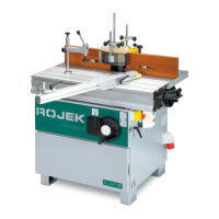
This document describes the ROJEK FSN 300A Single-Spindle Milling Machine, a woodworking machine designed for milling operations on wood or wood-based materials. It features a tilting spindle and a sliding table, making it suitable for various milling tasks.
Function Description
The FSN 300A is a vertical milling machine with manual workpiece feeding. Its primary function is to mill semi-finished products using a vertical, height-adjustable, and tiltable spindle. The machine is designed for operation by a single worker. It can perform longitudinal milling, milling with mechanical feed, and specialized milling for narrow workpieces (tenon jointing) and workpieces with small cross-sections. A dedicated cover for milling bends is also available, allowing for the creation of formed, rounded, and circular profiles.
Important Technical Specifications
The FSN 300A offers various configurations regarding motor power, operating voltage, and spindle types.
Motor Power Options:
- 2.2 kW (1 phase)
- 3 kW (3 phases)
- 3.7 kW (3 phases, 3 x 400 V)
Operating Voltage:
- 1 x 230 V
- 3 x 230 V or 3 x 400 V
- Frequency: 50 or 60 Hz
Spindle Specifications:
- Spindle diameter: 30 [35; 40; 50; (5/4)“; (5/4)"/(3/4)"] mm
- Spindle rotating speeds: 2,500, 3,500, 6,000, 8,000, 10,000 RPM
- Max. spindle lift: 140 mm
- Spindle length: 130 mm
- Spindle tilt: -45° to +5° (tilting from vertical to +5° is possible after pushing the backstop)
- Max. diameter of hole in table: 220 mm
- Max. tool diameter under table: 175 mm
- Max. tool diameter above table: 200 mm
Machine Dimensions (approximate):
- Length: 1155 mm (1755 mm with CV 310 long 1m, 1755 mm with CV 310 long 1.6m)
- Width with supporting table: 1375 mm (2055 mm with CV frame)
- Table height: 892 mm
- Max. machine height: 1300 mm
- Table dimensions: 1000 x 370 mm
- Exhausting nozzle diameter: 100 mm
- Weight (with CV long 1m): 240 kg (can be heavier depending on specifications)
Noise Specifications (EN 848-1:1999; ISO 7960:1995):
- Level of noise LpAeq (without tool): 70.4 dB(A)
- Level of noise LpAeq (with tool): 83.0 dB(A)
- Level of acoustic output LWA (without tool): 78.6 dB(A)
- Level of acoustic output LWA (with tool): 88.5 dB(A)
Sliding Table CV 310:
- Long 1m: Table dimensions 1000 x 310 mm, travel length 1295 mm
- Long 1.6m: Table dimensions 1600 x 310 mm, travel length 1900 mm
Exhaustion System Requirements:
- Minimum exhaustion capacity: 570 m³/hour (dry particles), 790 m³/hour (wet particles)
- Minimum air speed in pipes: 20 m/s (dry particles), 28 m/s (wet particles)
Usage Features
Operation and Adjustments:
- Height Setting: Spindle height is adjusted via a handwheel and fixed with an arresting rose. A measure scale in a see-through window indicates the height.
- Tilting: The spindle can be tilted from -45° (beyond the ruler) to +5° (towards the operator) from vertical. Tilting to +5° requires pushing the backstop. A fixing lever is released, and a handwheel is used for tilting, with the angle shown on a gravitational indicator.
- Guide Rulers: Guide rulers of the protection cover are set by releasing screws and adjusting their position. The gap between rulers is set after handles are released. The cross guide ruler on the sliding table CV can be set for perpendicular position or tilted from 0° to 45° using a measure scale. Workpiece width stoppers are adjustable along the cross-ruler.
- Change of Revolutions: The machine's cover of gears is electrically blocked for safety. Revolutions are changed by releasing the V-belt, shifting it to a new position, and re-tightening. A diagram on the cover indicates allowed revolutions for different tool diameters.
- Milling Operations:
- Longitudinal Milling: Requires suitable tools with defined chip thickness for manual feeding. Workpieces must be fed firmly and evenly. Guide rulers should never be adjusted while the machine is operating.
- Milling with Mechanical Feed: Uses suitable tools for manual or partially mechanical feed. The feeding device is set at a slight angle to guide the workpiece safely.
- Milling Narrow Workpieces (Tenon Jointing): Utilizes a feeding table and tool cover for safe movement of the workpiece. An aid is recommended for short pieces.
- Milling Small Cross-Section Workpieces: Requires suitable tools and a pressing piece to firmly hold the workpiece against the ruler and table.
- Cover of the Tool for Milling Bends: This device allows for milling formed, rounded, and circular profiles using a form plate guided along a guide ring. The guide ring's height is adjustable relative to the tool. The cover's transparent part presses the workpiece to the table and covers the tool.
Safety Instructions:
- The machine is equipped with various safety devices, but operators must read and understand all instructions before use.
- DANGER warnings indicate procedures that, if not followed, may result in death or serious injury.
- WARNING alerts to improper procedures that may cause harm to health, machine, environment, or economic losses.
- CAUTION advises care during activities to prevent minor injuries or machine damage.
- Operators must wear appropriate safety gear (goggles, apron, safety shoes, helmet, protective mask for dust). Loose clothing, jewelry, and long hair must be secured.
- The machine must not be operated under the influence of drugs or alcohol.
- Always ensure safety items are active and functioning before connecting to the mains.
- Do not touch rotating tools or electrical devices.
- Always switch off and lock the main switch or disconnect power before cleaning, maintenance, or when not in use.
- The vertical spindle must turn anticlockwise (to the left) against the material. Machining in the same direction is forbidden.
- Damaged power supply cables must be replaced immediately by a competent specialist.
- The electric motor is equipped with an electric brake that stops the machine within 10 seconds. If it fails, the machine must not be used.
- The emergency stop controller (D) must be released after use by turning its mushroom-like head.
- A motor brake releasing switch (F) can be used for easier tool manipulation.
Maintenance Features
General Maintenance:
- All maintenance work must be performed by qualified staff who have thoroughly read the instructions.
- Always disconnect the machine from the mains (switch off and lock the main switch or pull the plug) before any maintenance or repair work.
- Only specified kinds of lubricating oils and grease should be used.
- Do not use compressed air to clean the machine or remove chips.
- Keep the maintenance and working areas clean.
V-belt Tightening:
- The V-belt of the milling machine needs to be tightened periodically. This involves opening the gear cover (which electrically switches off the machine), releasing the belt by lifting the tightening lever, adjusting the motor holder to increase the distance between the motor pulley and spindle axes, and then reassembling and re-tightening the belt. The belt should sag by about 10 mm when pressed with a force of approximately 20 N.
Cleaning and Lubricating:
- The machine, rods, pins, threads, and other parts susceptible to corrosion should be cleaned and lubricated with suitable oil at least once a month.
- Electric motor and milling spindle bearings have permanent grease filling and do not require lubrication.
- Tables should be cleaned from resin with a suitable solvent.
- Avoid oil or grease contamination on belts; clean with paper if it occurs.
- Dust removal with a vacuum cleaner should be performed regularly, at least once a week.
Greasing Points (Table of Greasing Periods):
- Spindle bearings (1): Grease by spreading (after... hours). Plastic grease or oil: LV-2-3, Equivalent: ISO-L-XCBEA 3.
- Movement bolts (2): Grease by spreading (after... hours). Plastic grease or oil: LV-2-3, Equivalent: ISO-L-XCBEA 3.
- Cylinder seating of the milling machine spindle, tilting pins etc. (3): Lubricate with an oil can (50). Plastic grease or oil: OL-B5, Equivalent: ISO - LAN 68.
- Table plates (4): Lubricate with an oil can (8). Plastic grease or oil: OL-B5, Equivalent: ISO - LAN 68.
- Spindles and flanges (distance rings) (5): Lubricate with an oil can if not fitted with tools or if the machine is out of operation. Plastic grease or oil: OL-B5, Equivalent: ISO - LAN 68.
Troubleshooting:
- Machine does not work: Check electrical wiring and mains connection.
- Machine output is low: Check for blunt tools, excessive chip thickness, loose V-belt, or motor issues (call an expert).
- Machine vibrates: Check tool sharpening/adjustment, tool balance, machine setting, and anchoring.
- Recess on machined workpiece: Check for uneven lower guiding surface, incorrectly adjusted guide rulers, or improper material pressing/guiding.
Exchangeable Spindle Maintenance:
- Keep all spindle parts clean and intact. When not mounted, lubricate with engine oil.
This comprehensive overview covers the essential aspects of the ROJEK FSN 300A, from its intended use and technical capabilities to its operational procedures and maintenance requirements, emphasizing safety throughout.