BASIC LEVEL INSTALLATION & OPERATION
The following instructions describe a simple way to set up and operate a NOVA wireless system.
REGISTERING TRANSMITTER ADDRESSES IN RECEIVER :
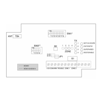
Note : Of the two dip-switches present on the PCB (SW1 and SW2), only SW1 is used for the basic installation mode.
1. Ensure all dipswitches are in OFF position.
2. Set SW1 position 7 to ON.
è All LEDs blink. Then Zone 1 LED blinks and TX1 LED blinks or lights steadily (either condition is acceptable). Steady TX LED means location has
no transmitter address programmed.
3. Send WRITE transmission from a transmitter. (See Table 1)
è All LEDs blink and buzzer sounds. Addressing of TX1 has been completed.
4. To proceed to TX2 or other transmitters press push-button S2 until LEDs indicate desired zone and transmitter number.
è Zone LED blinks and TX LED blinks or lights steadily.
5. Send WRITE transmission from another transmitter.
è All LEDs blink and buzzer sounds.
6. Continue to step through the LEDs by pressing S2 and sending WRITE transmissions until all transmitters have been written in the receiver (up to 4
transmitters per zone). Set SW1 position 7 to OFF.
è All LEDs will flash once and then extinguish.
Table 1: Summary instructions for making transmitters send a WRITE transmission:
NOVA-20 & NOVA-90 Set jumpers to WRITE Mode, then press Tamper Switch for over 3 seconds.
NOVA-30 Press push button on internal transmitter board for over 3 seconds.
NOVA-42, 43, 50, 51,52,53 & 61 Press push button for over 3 or 5 seconds as directed by device installation instructions.
NOVA-70 Disconnect and reconnect battery.
NOVA-71 & NOVA-91 (Available shortly)
Press Tamper for at least 3 seconds.
COMMUNICATION LINK TEST
Mount transmitters in their intended locations, then test communications as shown below.
The strength of the transmission is measured by the number of LEDs. Two LEDs is minimum acceptable transmission level.
Note: Output relays do not operate in this mode.
1. Cover must be removed during communications test.
2. Set SW1 position 7 to OFF and position 8 to ON.
è The LEDs blink, indicating COMMUNICATION MODE.
3. Operate each transmitter
è The zone and transmitter LEDs corresponding to each transmitter will light-up and the buzzer will sound to confirm communication. The red event
LEDs will indicate the relative quality of the RF transmission link. If there is no response or if less than 2 LEDs light-up when a transmitter sends a
signal, move the transmitter or receiver to a different location and try again. Confirm reception from all transmitters before ending the communication
test. Each transmitter resets earlier transmission results.
4. Set SW1 positions 7 and 8 to OFF. Replace the cover.
Replacing cover automatically puts receiver in NORMAL MODE.
Note: For Nova T50, 51, 52, 53 & 61 press the button of the transmitter for only 2 to 3 seconds after the red LED has lit up.
BASIC LEVEL OPERATION MODE
In this mode, reception of a signal from a transmitter will cause the green LEDs corresponding to zone and transmitter to blink. A red event LED or LEDs will
also blink to indicate the type of transmission, i .e. Alarm, Tamper, or Low Battery. Interference or jamming on the radio frequency channel will be indicated by
the two bottom red LEDs blinking according to SW2 settings. See Trouble Output Operation.
Alarm signals will cause a zone output contact to actuate for 2 seconds. Alternatively, if the alarm comes from a NOVA Universal Transmitter, a NOVA Smoke
Detector, or a NOVA restorable type transmitter, the zone output contact will latch until a restore signal is received, indicating that the alarm situation is no
longer present.
Perform a functional test of the system by causing each transmitter to alarm, and noting proper response from the receiver and control panel.
ADVANCED LEVEL INSTALLATION
Remove the cover by inserting and twisting a screwdriver in the slots along the upper or lower edge of the receiver.
Mount the NOVA receiver at the highest point close to the control panel. Connect the antenna to the left terminal of TB4.
Set all positions on dip-switches SW1 and SW2 to OFF.
Wire the NOVA receiver to the control panel as shown in Figure 2.
Connect the Arm Follow output of the Control Panel to the ARM terminal on the receiver.
If this output gives a low or Ground signal when the panel is armed, set position 3 of SW1 to OFF.
If the Arm Follow output gives a high or open signal when the control panel is armed, set position 3 of SW1 to ON.
If the ARM connection is not used, position 3 remains OFF.
ADVANCED LEVEL INSTALLATION & OPERATION
The dip-switch positions and supervision jumper are described in Table 2 and Table 4 below.
Table 2 : Configuration Dip-switch SW1 (8 Positions)
Position Description Comments
1
MOMENTARY mode
LATCH mode
OFF : During disarm only, upon memory activation, will display last 10 events by zone and
transmitter. See: Event Retrieval From Memory.
ON : During disarm only, will display, zone by zone, all the transmitters that were activated
with an indication of the events that occurred since the last arming. See: Event Retrieval From Memory.
2
Zone outputs polarity OFF : Zone outputs are Normally Closed.
ON : Zone outputs are Normally Open.
3
ARM input polarity OFF : Used if ARM FOLLOW output from panel is low (ground) when panel is armed.
ON : Used if ARM FOLLOW output from panel is high (or open) when panel is armed.
4
SUPERVISION
ARM/DISARM option
ON : During WRITE mode, for supervised transmitters (NOVA 20, 30, 70, 71, 90, 91).
ON : During NORMAL mode for Zone 1 only.
5
EXIT/ENTRY DELAY ON : During WRITE mode when ON, an alarm signal within 30 seconds of arming will be
ignored. Output due to an alarm signal received more than 30 seconds after arming
will be delayed by 30 seconds and cancelled if receiver is disarmed during this period.
6 NOT 24 HOURS ON : During WRITE mode, alarm signals received when receiver is disarmed will be ignored.
7, 8
OPERATIONAL MODES :
NORMAL MODE:
WRITE MODE:
COMMUNICATION MODE:
APPLICATION MODE:
SW1 SETTINGS
7 OFF, 8 OFF Normal operation
7 ON, 8 OFF Used to register transmitter addresses in receiver.
7 OFF, 8 ON Used to test communication with transmitters.
7 ON, 8 ON Used to verify configuration of each transmitter.
Note : When receiver is armed the display will not light-up.
 Loading...