11
Parameter Guide
TONE MFX Group B TONE MFX Group B
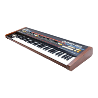
JD-800JD-800
This can only be used when a tone from the JD-800 model is
selected for part 1.
Parameter Value Explanation CC#
Seq Sequence
Selects the order in which the eects
are connected.
CHO: Chorus
DLY: Delay
REV: Reverb
DL Switch OFF, ON Turns the delay on/o.
CH Switch OFF, ON Turns the chorus on/o.
RV Switch OFF, ON Turns reverb on/o.
DelayDelay
DL C Sync sw OFF, ON
Turn this on to synchronize the delay
times of the left, center and right delay
sounds with the tempo.
DL L Sync sw OFF, ON
DL R Sync sw OFF, ON
DL C Time 0.1–600.0
When each Sync Sw is o, the delay
times of the left, center and right
delay sounds can be set irrespective
of tempo.
DL L Time 0.1–600.0
DL R Time 0.1–600.0
DL C Note
1/64T, 1/64, 1/32T,
1/32, 1/16T, 1/32.,
1/16, 1/8T, 1/16.,
1/8, 1/4T, 1/8., 1/4,
1/2T, 1/4., 1/2, 1T,
1/2., 1, 2T, 1., 2
When each Sync Sw is on, the delay
times of the left, center and right delay
sounds can be set by note length.
DL L Note
DL R Note
DL C Level 0–100
Sets the levels of the left, center and
right delay sounds.
94
DL L Level 0–100 92
DL R Level 0–100 95
DL Feedback -98%–98%
Sets the feedback value, which is how
much of the center delay output signal
is sent back to the eect input. Set
what percentage of the normal phase/
reversed phase (+/-) of the output
signal goes back to the input. When
this is set to “0”, no feedback is applied.
When the center delay sound is fed
back, the delay sounds fed back from
the left and right will be input as well.
ChorusChorus
CH Rate 0.1Hz–10.0Hz
Sets the rate of modulation for the
chorus. Higher values produce a faster
rate.
CH Depth 0–100
Sets the depth of modulation for
the chorus. Higher values produce a
greater modulation depth.
CH Delay 0.1–50.0
Sets the delay time for the chorus. This
sets the time it takes from the start of
the original sound to when the chorus
eect begins. Larger values produce
longer delays, creating a wider sound.
CH Feedback -98%–98%
Sets the feedback value, meaning how
much of the chorus output signal is
sent back to the eect input. Set what
percentage of the normal phase/
reversed phase (+/-) of the output
signal goes back to the input. When
this is set to “0”, no feedback is applied.
CH Level 0–100 Sets the chorus volume. 93
Parameter Value Explanation CC#
ReverbReverb
RV Type
ROOM1, ROOM2,
HALL1, HALL2,
HALL3, HALL4,
GATE, REVERSE,
FLYING1, FLYING2
Selects the reverb type. Use
this to select the reverberation
characteristics, which are a result of
the hall size, wall materials and so on.
ROOM1/2: A reverb that simulates a
room. ROOM2 has a more reective
and brighter sound than ROOM1.
HALL1–4: A reverb that simulates a
concert hall. Types 1–4 dier in room
size, reections and so on.
GATE: A reverb to which a gate is
applied. This mutes the reverberations
at a xed time.
REVERSE: Makes the reverberations
grow louder and then mute at a xed
time.
FLYING1/2: Pans the reverberations
from left to right (FLYING1) or right to
left (FLYING2).
RV Pre dly time 0–120
This sets the pre-delay time, meaning
the time it takes for the reverberations
to sound after the original sound is
heard.
Larger values give an impression of
being in a larger room.
RV ER Level 0–100
Sets the sound level of the direct
reections from the walls and the early
reections after the original sound is
produced. This indicates the distance
from the sound source (the original
sound) to the walls. Larger values
indicate a shorter distance to the walls.
* This parameter is disabled if the “GATE”,
REVERSE”, or “FLYING1/2” types are
selected.
* The early reection level and reverb level
work separately. For this reason, the early
reection can still be heard even when
the reverb level is “0”.
RV HF Damp 500Hz–BYPASS
Sets the frequencies to cut in the
high-frequency portion of the
reverberation.
The high-frequency portion of reverb
sounds decays dierently depending
on the wall material. This parameter
simulates this kind of high-frequency
decay.
RV Time
0.1–20.0 s (*1)
5–500 ms (*2)
Sets the reverberation time. Higher
values produce longer reverberations.
* 1 Reverb Type: ROOM1/2, HALL1–4
* 2 Reverb Type: GATE, REVERSE, FLYING1/2
13
RV Level 0–100 Sets the reverberation volume. 91
OutputOutput
Balance
D100:0W–
D0:100W
Sets the volume balance between the
dry sound (D) and the eect sound
(W).
Level 0–127 Sets the volume level. 12