Do you have a question about the Roland VK-9 and is the answer not in the manual?
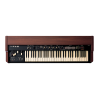
Details on keyboard, drawbars, presets, percussion, controls, power, dimensions, and weight for the VK-9.
Keyboard, dimensions, weight, and accessories for the VKP-9 pedal unit.
Seat, stand, back rail, knob bolt, assembly dimensions, and weight for the VKB-9 bench.
Connection cord and dimensions for the VKE-1 expression pedal.
Circuit diagrams for the Upper Keyboard Keying IC Tone Gate (AGH-13/14).
Circuit diagrams for the Lower Keyboard Keying IC, Tone Gate, and Divider (AGH-11/12).
Visual guide to identifying Tone Gate Keying ICs and their connections on circuit boards.
Detailed explanation on finding specific keyer ICs based on legends and foil patterns.
Circuit diagram and component layout for the Master Oscillator module.
Circuit diagram and component details for the sustain control section.
Circuit diagram and component details for the selector switch functions.
Diagram for the Tone Generator Driver circuit.
Circuit diagrams for the Drawbar Gate modules.
Circuit diagram for the Drawbar Power Supply.
Diagram for the Preset circuit.
Circuit diagram for the Synthesizer Percussion Control module.
Circuit diagrams for the Bass section, including BAH-19A and BAH-19B.
Circuit diagrams for the Filter modules FLH-13 and FLH-14.
Circuit diagrams for the Preamplifier module.
Diagrams for various Power Supply boards (PSH-17 to PSH-22).
Visual guide for disassembling the unit and identifying component locations.
Instructions and points for electrical adjustments and settings.
Detailed breakdown and identification of keyboard components.
Diagrams and part numbers for Expression Pedal VKE-1 and Pedalboard VKP-9.
Comprehensive list of all parts used in the VK-9 and VK-6 systems.
| Type | Combo Organ |
|---|---|
| Sound Engine | Virtual ToneWheel |
| Keyboard | 61 keys |
| Drawbars | 9 drawbars |
| Effects | Chorus, Reverb, Overdrive |
| Control | Vibrato Chorus |
| Connections | MIDI In/Out |
| Power Supply | AC adapter (included) |