3
Panel Description
Top Panel
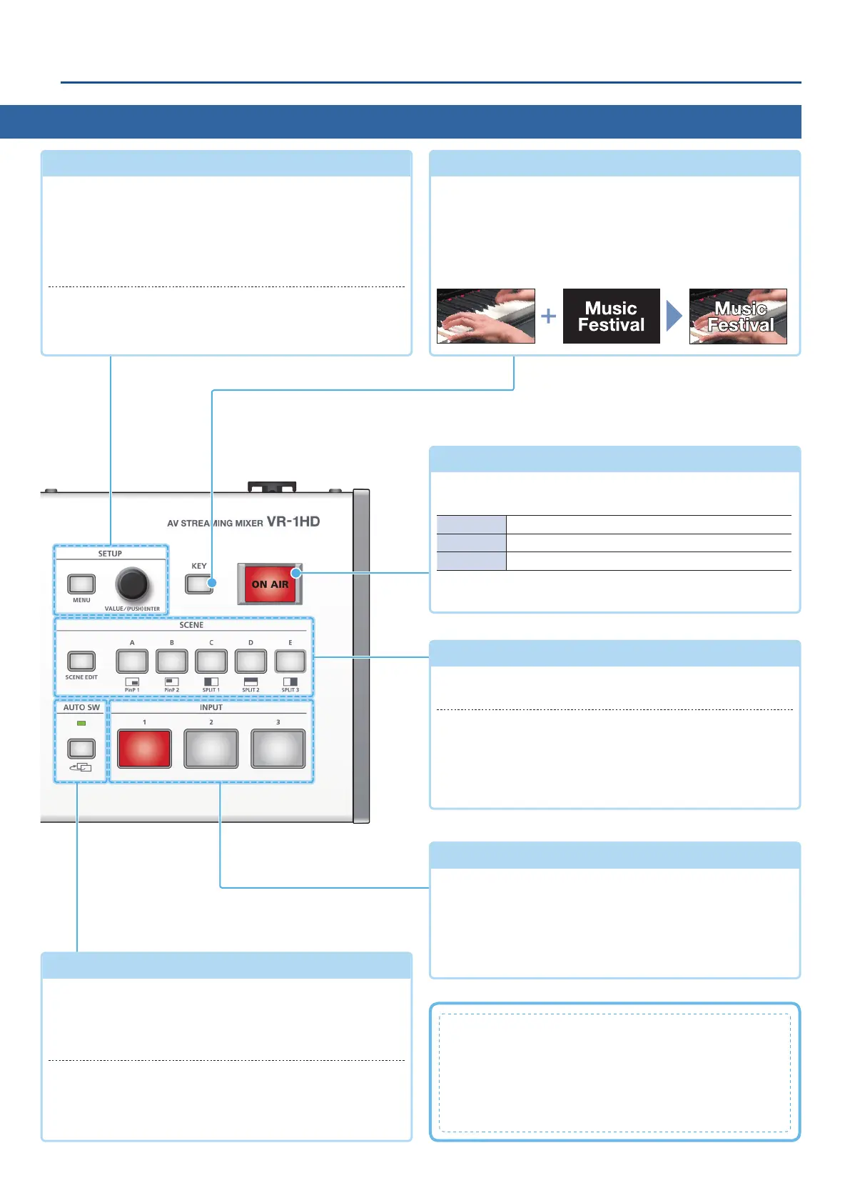
AUTO SW area
(p. 10)
[AUTO SW] button
Turn the auto switching function on/o. If this is on (lit), the
INPUT 1–3 video and scenes A–E will switch automatically.
* Auto switching has three operating modes.
AUTO SW indicator
Lit green at the moment that auto switching switches the
video.
* Operates at all times, regardless of whether auto switching is on or o.
SCENE area
(p. 12)
[SCENE EDIT] button
Directly accesses the scene-related menu.
SCENE [A]–[E] buttons
Recall screen arrangements (scenes) that you’ve registered. The
selected button is lit red.
* When you select the INPUT [1]–[3] buttons, the scene selection is
cleared.
[ON AIR] button
(p. 14)
Fades-in/out the main output video.
The [ON AIR] button indicates the fade status.
Lit Normal output
Blinking Now fading-in/out
Unlit Faded out
* The fade-in/out eect does not apply to the video that’s output from
the MONITOR (MENU) connector.
What is the main output?
This is the video/audio output that is aected by all
processes such as video compositing and audio eects. It is
output from the MAIN connector.
This is the video that is seen by the people who are
watching the live stream or presentation.
SETUP area
(p. 6)
[MENU] button
When this is on (lit), the menu appears on the display that’s
connected to the MONITOR (MENU) connector.
If you’re in a lower level, this button returns to the next higher
level. If the highest menu level is shown, this button closes the
menu.
[VALUE] knob
Turn: Selects a menu item, or edits the value of a setting.
Press: Conrms the selected menu item or the edited value.
[KEY] button
(p. 14)
Turns on/o video compositing using a luminance key. When
on (lit), two videos are composited and output.
What is luminance key compositing?
This is a method of using brightness (luminance) information
to cut out a logo or image and overlay it on a background
image.
INPUT [1]–[3] buttons
(p. 10)
Switch the video that’s being input to the VIDEO INPUT 1–3
connectors. The selected button is lit red.
* When you select the SCENE [A]–[E] buttons, the input video
selection is canceled.
* Still images saved in this unit or single-color screens can also be
assigned to the INPUT [1]–[3] buttons.


 To Next Page