EasyManua.ls Logo

Rolex CALIBRE 3175 - Uncasing and Day-Date Calendar Mechanism Dismantling

Rolex CALIBRE 3175
39 pages
Print Icon
To Next Page IconTo Next Page
To Previous Page IconTo Previous Page
Loading...
9
9.
UNCASING,
DISMANTLING
THE
DAY
-DATE
CALENDAR
MECHANISM
AND
THE
MOVEMENT
9.1.
Remove
the
automatic
device
module
(No.
3135-145)
taking
out
the
2
screws
(No.
3135-5110)
of
the
automatic
device
module.
Dismantling
and
assembling
the
automatic
device
module,
see
pages
15
and
16.
9.2.
Unease
the
movement,
remove
the
hands
and
the
dial,
then
refit
the
winding
stem.
9.3.
Open
the
3
bolts
of
the
day
indicator,
remove
the
day
indicator
(No.
3155-17101,
respectively
No.
3155-17201),
open
the
bolt
of
the
date
indicator,
remove
the
date
indicator
(No.
3155-16100,
respectively
No.
3155-16200),
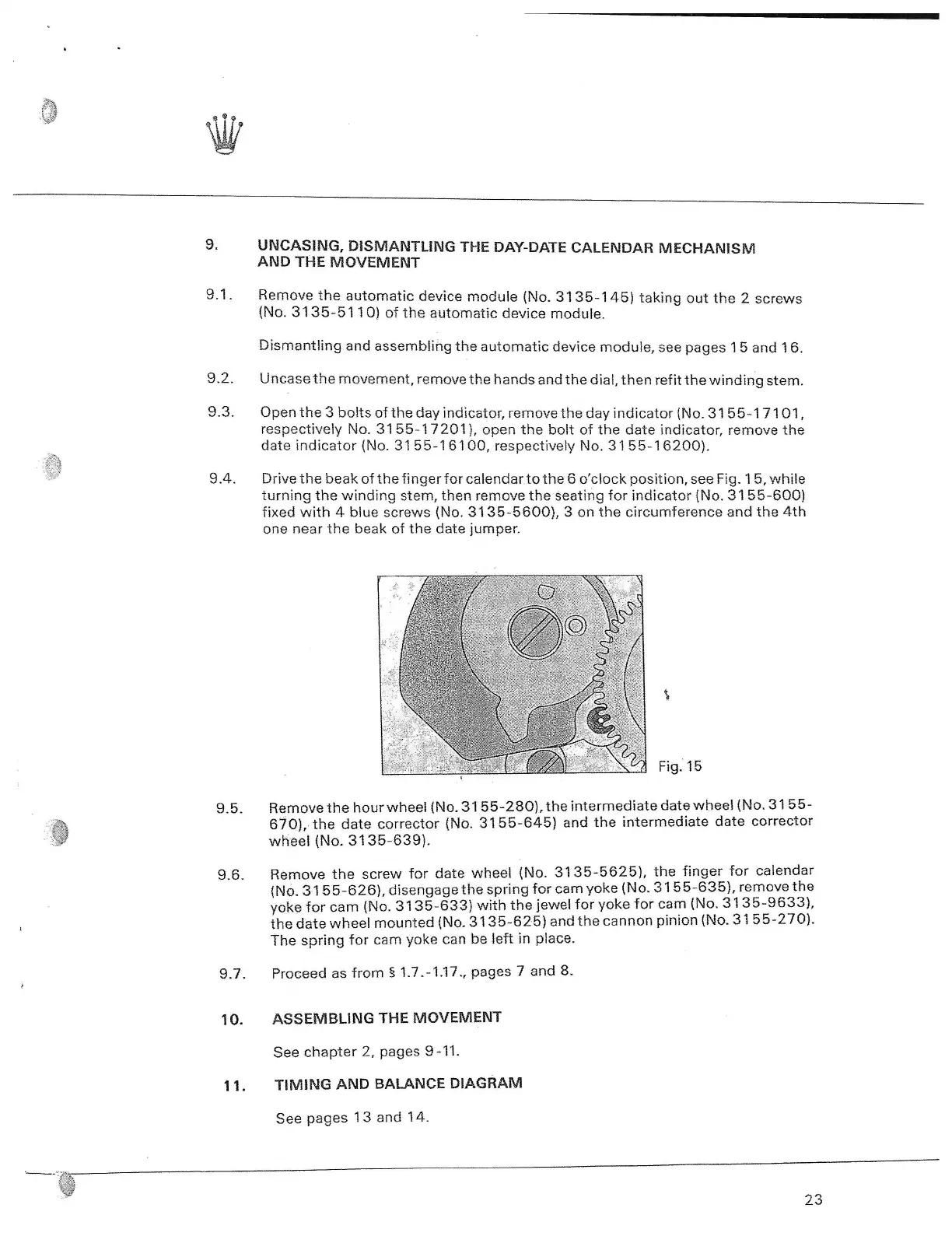
9.4.
Drive
the
beak
of
the
finger
for
calendar
to
the
6
o'clock
position,
see
Fig.
15,
while
turning
the
winding
stem,
then
remove
the
seating
for
indicator
(No.
3155-600)
fixed
with
4
blue
screws
(No.
3135-5600),
3
on
the
circumference
and
the
4th
one
near
the
beak
of
the
date
jumper.
Fig.
15
9.5.
Remove
the
hour
wheel
(No.
3155-280),
the
intermediate
date
wheel
(No.
3155-
670),
the
date
corrector
(No.
3155-645)
and
the
intermediate
date
corrector
wheel
(No.
3135-639).
9.6.
Remove
the
screw
for
date
wheel
(No.
3135-5625),
the
finger
for
calendar
(No.
3155-626),
disengage
the
spring
for
cam
yoke
(No.
3155-635),
remove
the
yoke
for
cam
(No.
3135-633)
with
the
jewel
for
yoke
for
cam
(No.
3135-9633),
th
e
date
wheel
mounted
(No.
3135-625)
and
the
cannon
pinion
(No.
3155-270).
The
spring
for
cam
yoke
can
be
left
in
place.
9.7.
Proceed
as
from
§
1.7.-1.17.,
pages
7
and
8.
10.
ASSEMBLING
THE
MOVEMENT
See
chapter
2,
pages
9-11.
11.
TIMING
AND
BALANCE
DIAGRAM
See
pages
13
and
14.
23

Table of Contents