13
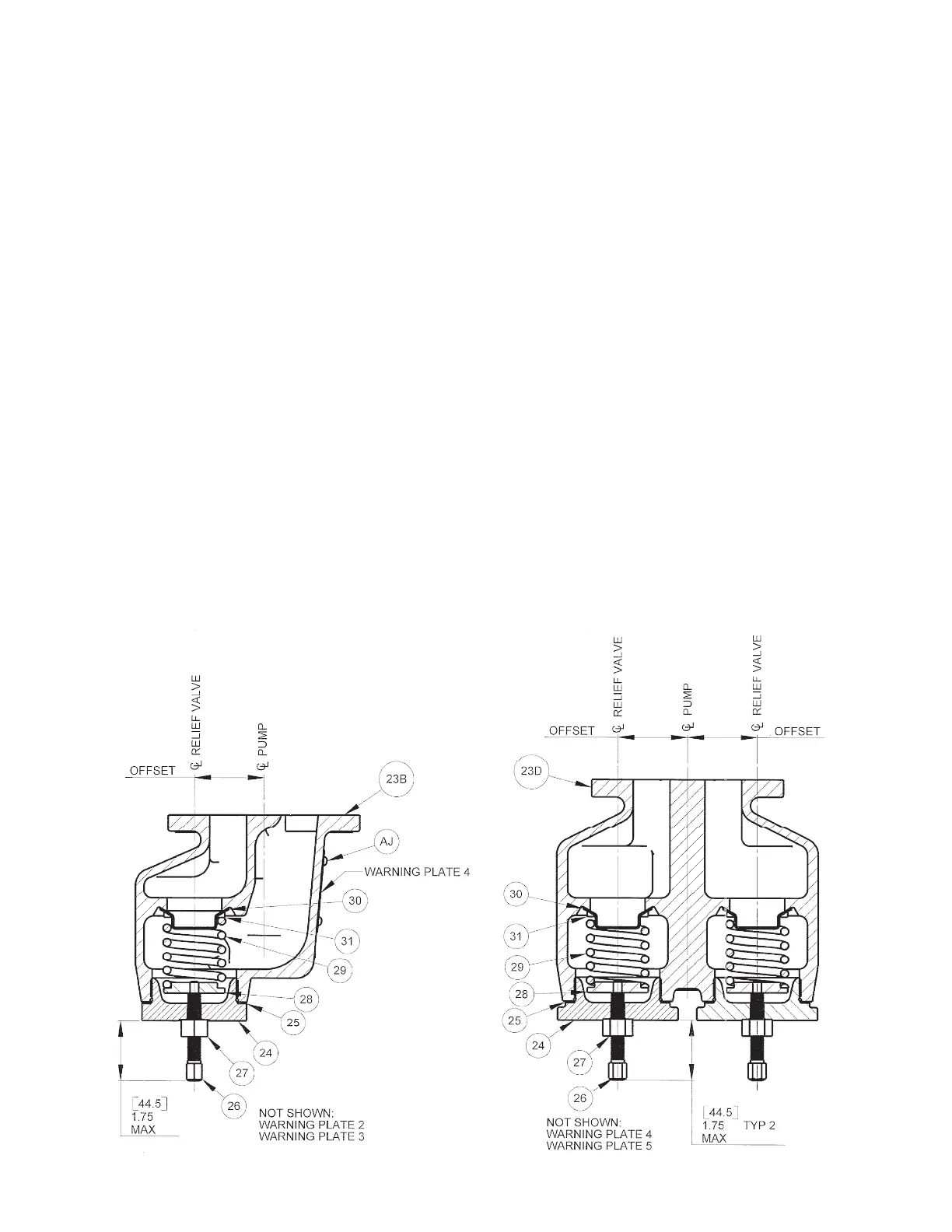
CHANGING THE RV STYLE RELIEF VALVE POSITION
Refer to the sectional drawing shown in Figure 5.7.
(Not required on a pump with the BV Style Bi-Directional Relief Valve).
You should have already checked the drawings in Figure 5.5 to find the correct way to position your relief valve,
based on the pump’s direction of shaft rotation and position and the location of the inlet and discharge ports. If you
have not checked, do it now to decide whether or not you should change the position of our relief valve.
If the relief valve position needs to be changed, follow the instructions below and refer to Section 14, PARTS LIST
and the RV STYLE SINGLE DIRECTION RELIEF VALVE drawing shown in Figure 5.7.
1. Turn off pump and lock out energy source to driver.
2. Close inlet and discharge valves.
3. To drain pump, follow procedure in Section 7, INSTRUCTIONS FOR DRAINING PUMP.
4. Remove two washer head cap screws (K) and eight hex head cap screws (L) securing faceplate (23B) to
case. Remove faceplate.
5. While viewing faceplate (23B) from end with relief valve cap (24), turn faceplate so that orientation of relief
valve cap to pump matches DIRECTION OF ROTATION drawing previously selected from charts in Figure
5.5.
6. Install two hollow dowel pins (J) on faceplate end of case (19A, B, C, D, E) if they were removed during
disassembly. Place appropriate number of case gaskets (20) on end of case. Align faceplate (23B) on
hollow dowel pins, maintaining proper orientation as determined above. Secure faceplate to case using
two washer head cap screws (K) and eight hex head cap screws (L).
RV STYLE SINGLE DIRECTION RELIEF VALVE BV STYLE BI-DIRECTIONAL RELIEF VALVE
FIGURE 5.7 FIGURE 5.8
 Loading...