EasyManua.ls Logo

Roper F Series - User Manual

Roper F Series
30 pages
Print Icon
To Next Page IconTo Next Page
Loading...
1
F SERIES TYPE 27
OWNERS MANUAL
G12-208
06/13/16
SAFETY INSTRUCTIONS
This is an industrial component. Only a qualified systems integrator should be allowed to
design it into a system. The integrator must determine proper plumbing, mounting, driveline
and guard components.
Improper installation or use could lead to a serious, even fatal, accident. The system
integrator must communicate all safe operation procedures to the end user(s).
Before operation, fully understand and follow the instructions shown in this manual and any
instructions communicated by the system integrator. No one should be allowed to operate or
maintain this pump that has not been fully trained to work safely according to the
configuration of the pump system and in accordance with all applicable government and
industry regulations.
DO NOT paint over nameplates, ID tags or warning tags.
Confidential & Proprietary: This document contains confidential and proprietary information which is the exclusive property
of Roper Pump Company, Commerce, GA. U.S.A. and shall not be reproduced, communicated, disclosed, or disseminated in
any manner to third parties or used for any purpose other than its intended purpose without prior written consent of the
management of Roper Pump Company.
Roper Pump Company
P.O. Box 269
Commerce, GA 30529 USA
Telephone: (706) 335-5551
TeleFAX: (706) 335-5490
Email: sales@roperpumps.com
www.roperpumps.com
Question and Answer IconNeed help?

Do you have a question about the Roper F Series and is the answer not in the manual?

Summary

Safety Instructions

Warnings and General Guidelines

System Pressure and Hazardous Fluids

Critical safety advice for managing system pressure and handling hazardous fluids.

Plumbing Guidelines

Guidelines for optimal pump plumbing to minimize suction losses and cavitation.

Mounting Base Requirements

Requirements for a rigid mounting base to ensure pump stability and shock absorption.

Pump and Drive Assemblies

Safety protocols for pump and drive assemblies, including guarding and codes.

Pump to Driveline Alignment

Importance of proper alignment to prevent premature pump shaft failure.

Roper Pumps Close Coupled Drives

Details on close-coupled drive units and their mounting to the pump.

Guarding PTO Drive Shafts

Essential safety measures for PTO drive shafts, emphasizing guarding.

Nameplate Data Identification

Figure (Model Number)

Explanation of pump nomenclature, focusing on the model number structure.

Specification (Spec)

Understanding specification numbers for unique pump configurations and applications.

Pump Type

Meaning of the pump TYPE number for internal identification and reference.

Serial Number

Identification of the unique serial number for pump tracking and support.

Maximum Pump Ratings

Pre-Operations Check

Recommended Tool List

Direction of Rotations

1 & 2 F1-F100 CW Rotations

Visual guide to clockwise rotation for 1 & 2 F1-F100 pump series.

1 & 2 F1-F100 CCW Rotations

Visual guide to counter-clockwise rotation for 1 & 2 F1-F100 pump series.

17 & 18 F10-F100 CW Rotations

Visual guide to clockwise rotation for 17 & 18 F10-F100 pump series.

17 & 18 F10-F100 CCW Rotations

Visual guide to counter-clockwise rotation for 17 & 18 F10-F100 pump series.

17 & 18 F1-F5 CW & CCW Rotations

Visual guide to CW and CCW rotation for 17 & 18 F1-F5 pump series.

1 & 2 F75-F300 CW & CCW Rotations

Visual guide to CW and CCW rotation for 1 & 2 F75-F300 pump series.

Lubrication

Relief Valve

Relief Valve Components and Chart

Diagram and chart detailing relief valve parts and dimensions.

Adjusting the Relief Valve

Step-by-step procedure for setting the relief valve pressure accurately.

Replace Spring;Piston or Change Pump Direction

Mechanical Seal

Packing

Parts List and Cross Sectionals

Overview

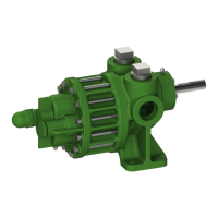
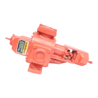
This document outlines the F Series Type 27 Owners Manual, providing essential information for the safe and effective operation and maintenance of Roper F Series pumps.

Function Description:

The Roper F Series Type 27 pump is an industrial component designed to transfer various liquids. It is a positive displacement pump, meaning it moves a fixed amount of fluid with each revolution. The manual emphasizes that this is an industrial component and should only be integrated into a system by a qualified systems integrator. The integrator is responsible for determining proper plumbing, mounting, driveline, and guard components, and for communicating safe operation procedures to the end-user.

Important Technical Specifications:

The manual includes a "Maximum Pump Ratings" table, which provides critical performance data for various F Series pump sizes. These specifications include:

  • Pump Size (F1 to F200): This indicates the nominal size of the pump.
  • Flow Rate (GPM): Ranging from 3.5 GPM for the F1 to 234.6 GPM for the F150 and 213.7 GPM for the F200.
  • Pressure (PSI): All listed pump sizes (F1-F200) are rated for a maximum pressure of 300 PSI.
  • Temperature (°F): The standard maximum operating temperature is 212°F. However, the manual notes that temperatures up to 250°F may be achieved using available material options, and advises consulting the factory for details.
  • Input Speed (RPM): This varies by pump size, from 3600 RPM for smaller pumps (F1-F20) down to 900 RPM for the F200.

The pump nomenclature provides further technical details:

  • Figure (Model Number): A five, six, or seven-digit number. The first (and sometimes second) digit indicates the mounting arrangement and relief valve (RV) presence:
    • 1 = Foot mounted, No RV
    • 2 = Foot mounted with RV
    • 17 = Flange mounted, No RV
    • 18 = Flange mounted with RV
    • 25 = Baseplate mounted, No RV
    • 26 = Baseplate mounted with RV
    • 33 = Close Coupled, No RV
    • 34 = Close Coupled with RV
  • The next digit is 'F' for F series.
  • The subsequent two or three digits indicate the approximate theoretical displacement in US gallons per 100 revolutions (or Liters/100 rev). Examples include F1 (.00086 GPM), F15 (.0103 GPM), F100 (.107 GPM), and F200 (.232 GPM).
  • The final letter indicates the direction of rotation and shaft position, with 'W' or no letter for clockwise (CW) and 'X' for counterclockwise (CCW) rotation, when facing the drive shaft end.
  • Spec: A specification number for unique configurations or modifications.
  • Type: An in-house identification number for construction and hydraulics.
    • Spec 0 - Mechanical Seal, Tapped Ports
    • Spec 5 - Packed Box, Tapped Ports
    • Spec 17 - Mechanical Seal, Flanged Ports
    • Spec 174 - Packed Box, Flanged Ports
  • Serial Number: A unique identifier for each pump.

Usage Features:

The manual provides detailed instructions for proper usage, including:

  • Pre-Operations Check: Before starting, users must read and understand the manual, disconnect the coupling between the driver and pump, test driver rotation, ensure the integral relief valve (if present) is correctly positioned and adjusted, and verify that the pump operates freely without binding. All guards must be in place, and inlet/discharge valves open before starting.
  • Plumbing Guidelines: Inlet pipes should be short and straight to minimize suction pressure losses and avoid cavitation. Plumbing weight, misalignment, or thermal expansion should not exert excessive force on the pump; proper support and expansion joints are recommended. A relief valve must be installed as close to the pump outlet as possible, before any shut-off valves, to prevent over-pressure. Thread seal tape is explicitly prohibited on pump port threads.
  • Mounting Base: The pump unit must be mounted on a rigid, heavy base to provide support and absorb shock. For concrete mounting, a steel baseplate is required to distribute mounting stress.
  • Pump and Drive Assemblies: Adequate guards must be installed to prevent contact with moving components, adhering to all OSHA, Federal, State, and local codes.
  • Alignment: Excessive misalignment between the pump and driveline can cause premature failure. Illustrations for parallel and angular misalignment are provided, emphasizing the importance of proper coupling alignment. For close-coupled drives, alignment is maintained by the assembly itself.
  • Direction of Rotations: Detailed illustrations are provided for various pump models (1 & 2 F1-F100, 17 & 18 F10-F100, 17 & 18 F1-F5, 1 & 2 F75-F300) showing both clockwise (CW) and counterclockwise (CCW) rotations, along with corresponding inlet and discharge port orientations. It is crucial to ensure the shaft rotation, pipe connections, and relief valve position match the desired direction of rotation.
  • Relief Valve Operation: The relief valve must be positioned according to the desired direction of rotation to function correctly. It is factory-set for full bypass at a differential pressure of 300 PSIG (20.7 BAR) at 900-1800 RPM for liquids with 150-300 SSU viscosity. However, the user is responsible for setting the relief valve based on the specific liquid viscosity, specific gravity, flow rate, and pump RPM. Built-in relief valves sense differential pressure only. Prolonged operation with a fully bypassing relief valve can cause liquid heating and potential damage.

Maintenance Features:

The manual includes instructions for maintaining key pump components:

  • Lubrication: All lubrication fittings are greased at the factory. Internal pump parts are lubricated by the pumped liquid. The outboard bearing or bearing cage should be greased with ball bearing grease once a month in daily service or equivalent in intermediate service.
  • Relief Valve Adjustment: A detailed procedure is provided for adjusting the relief valve, including connecting a pressure gauge, removing the seal cap and gasket, loosening the locknut, backing out the adjusting screw to a specified "A" dimension (chart provided for different pump sizes), starting the pump, slowly closing the discharge line, turning the adjusting screw clockwise to achieve the desired pressure, tightening the locknut, replacing the gasket and seal cap, and opening the discharge line.
  • Relief Valve Spring/Piston Replacement or Rotation Change: Instructions cover shutting off the pump, removing the seal cap and gasket, loosening the locknut, adjusting relief valve pressure to minimum, removing the bonnet and gasket, removing the plug cap and gasket, checking parts for cleanliness, determining rotation direction, placing the poppet and spring correctly, assembling the spring guide and gasket, tightening the bonnet, reinstalling the gasket and plug cap, and readjusting the relief valve.
  • Mechanical Seal Maintenance: Mechanical seals do not require adjustment. Leakage indicates wear, damage, or hardening of components. When replacing, care must be taken not to mar or scratch sealing surfaces or damage bellows. Used seals should only be re-serviced if sealing surfaces are perfectly flat and smooth. Specific replacement procedures are provided for F1-F5 pumps (removing key, cap screws, bearing cage, gasket, cleaning shaft, lubricating with light machine oil, sliding rotating element, checking lip seal) and F10-F300 pumps (removing retaining ring or loosening set screws, removing retaining ring from bearing cage, removing cap screws and bearing cage, cleaning shaft, lubricating with light machine oil, sliding rotating element, checking stationary seat and O-ring, installing gasket and bearing cage, securing with cap screws, installing retaining ring or tightening set screws).
  • Packing Maintenance: After a short run-in period, packing should be examined for leakage. Slight leakage (5-10 drops per minute) is normal and necessary. Excessive leakage requires stopping the pump and adjusting the gland nuts evenly in 1/6 to 1/3 turn increments. Overtightening can score shafts, increase torque, and damage couplings. To replace packing, remove nuts, clips, packing gland, and packing rings (using packing hooks), clean the shaft, and replace if worn. New rings should be staggered 180 degrees and tamped firmly. The packing gland should be adjusted whenever leakage exceeds ten drops per minute, with regular checks depending on service type.

Safety Warnings:

The manual prominently features several warnings:

  • Over-pressure: May burst pump or system components. Always include a relief valve. Do not over-pressurize or block the discharge line.
  • Injection Hazard: Do not stop leaks with hands. Escaping fluid can penetrate skin and cause serious injury. Seek medical attention immediately if exposed.
  • Hazardous or Toxic Fluids: Can cause serious injury.
  • Guarding: Operating without guards can result in serious injury or death from moving machinery. Do not operate without adequate guards.
  • Nameplates/Tags: DO NOT paint over nameplates, ID tags, or warning tags.
  • Shaft Packing Adjustment: Failure to stop the pump before adjusting shaft packing can cause serious injury or death.
  • Relief Valve Adjustment: Take precautions to prevent personal injury or physical damage from product loss during adjustment.
  • Relief Valve Poppet: Periodically check that the poppet slides freely. Binding or foreign material can cause excessive pressure buildup.

This comprehensive manual ensures users have the necessary information for safe operation, troubleshooting, and maintenance of their Roper F Series Type 27 pumps.

Roper F Series Specifications

General IconGeneral
BrandRoper
ModelF Series
CategoryWater Pump
LanguageEnglish

Related product manuals