10
PROPER PUMP GEAR ROTATION
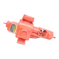
Proper gear rotation is shown on the warning tags attached to the relief valve faceplate.
PUMP INLET and PUMP DISCHARGE
On the RV and BV style relief valve, either the “pump inlet” or “pump discharge” arrow will always point directly to
one side port on the cases that have one side port and one top port. The top port is connected to the side of the
pump that is opposite the side port. The “pump inlet” and “pump discharge” arrows will always point directly to the
inlet and discharge ports on the pump with straight through port cases.
An integral relief valve should not be used on applications where the discharge must be closed for more than one
minute. Prolonged operation of the pump with the discharge closed will cause rapid heating of the liquid circulating
through the relief valve, thus resulting in possible damage.
DIRECTION OF ROTATION FOR THE RV STYLE RELIEF VALVE
The drawings showing DIRECTION OF ROTATION FOR PUMP CONFIGURATIONS USING THE RV STYLE
RELIEF VALVE and position of relief valve with the letter “L” in the designation are for low drive applications (the
drive shaft is lower than the side port). All other drawings shown in Figure 5.5 are for high drive applications (the
drive shaft is above the side port).
The arrow in the drawing at the end of the drive shaft indicates the direction of rotation needed to achieve proper
operation of the pump and relief valve when using the pump and relief valve orientation shown in the drawing. CW
indicates clockwise rotations and CCW indicates counterclockwise rotation when viewed from the drive shaft end
of the pump.
To determine the correct relief valve position for any of the pump orientations, use the drawings shown in Figure
5.5 titled DIRECTION OF ROTATION FOR PUMP CONFIGURATIONS USING THE RV STYLE RELIEF VALVE:
1. Find the group of drawings with the proper drive shaft position (high or low drive). Drawings with W, Z, X,
or Y rotation are high drive pumps. Drawings with LW, LZ, LX, or LY rotation are low drive pumps.
Eliminate all other drawings.
2. In the drawings remaining, find the group of drawings with the proper direction of rotation arrow at the end
of the drive shaft. Eliminate all other drawing. CW indicated clockwise rotation and CCW indicates
counterclockwise rotation when viewed from the drive shaft end of the pump.
3. In the drawings remaining, find the group of drawings with the proper port positions (straight through or
right angle). Eliminate all other drawings.
4. In the remaining drawings, find the drawing with the proper inlet and discharge port locations. This drawing
will show the proper relief valve position for the pump configuration chosen. Note the position of the word
“INLET” cast on the side of the relief valve faceplate. The word “INLET” must be on the inlet “side” of the
pump in order for the relief valve to work properly. The discharge and inlet “sides” of the pump are always
directly opposite each other; the top port of the right angle pump is connected to the “side” of the pump via
an internal passage.
 Loading...