Do you have a question about the Rose electronics GTS and is the answer not in the manual?
Lists various components like tubes, couplings, hinges, and joints for the suspension system.
Illustrates the load capacity of the suspension system.
Describes the adjustment mechanism of the unit.
Details the mounting process and specifications for the coupling component.
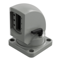
Details the mounting process and specifications for the angle coupling component.
Details the mounting process and specifications for the wall hinge.
Details the mounting process and specifications for the flange coupling.
Details the mounting process and specifications for the top mounted joint.
Details the mounting process and specifications for the angle component.
Details the mounting process and specifications for the stand foot.
Details the mounting process and specifications for the DN coupling.
Details the mounting process and specifications for the inclining adapter.
Details the mounting process and specifications for the turnable stand foot.
Details the mounting process and specifications for the 15° coupling.
Details the mounting process and specifications for the 15° angle coupling.
Details the mounting process and specifications for the Siemens PRO coupling.
Details the mounting process and specifications for the Siemens PRO angle coupling.
Details the mounting process and specifications for the flat panel adapter.
| Brand | Rose electronics |
|---|---|
| Model | GTS |
| Category | Racks & Stands |
| Language | English |