9
-- 5) TECHNICAL DESCRIPTION --
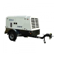
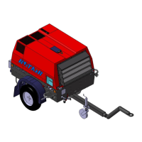
-- 5.1) CHASSIS AND CANOPY --
The chassis and the canopy are made of shaped and electro-welded sheet. Both parts are subject to two
painting treatments to guarantee the corrosion and rust proofness. The canopy has been planned to meet all
requirements of an ordinary and extraordinary maintenance : it is equipped with big doors on all sides to
guarantee an easy accessibility to the main parts of the machine.
-- 5.2) MOTOR --
Three-phase, 2 poles, class F insulation, IP 55 protection degree. For further technical data and operating
and maintenance instructions, please refer to the enclosed manual of the motor.
-- 5.4) COMPRESSION UNIT AND OIL SEPARATOR TANK --
It is completely manufactured in the ROTAIR S.P.A. factory and consists of a central body (cylinder) inside
which are fitted two screw rotors with asymmetric section, a male one with 5 lobes and female one with 6
lobes.
The cylinder is closed at the ends by two head sections which contain the bearings which bear the radial and
axial loads created by the air compression. A series of channels, inside the cylinder and heads, undertake to
deliver the oil to the various components. The distribution of the lubricant , serves to lubricate the bearings
and to maintain a coating of oil between the rotors and the bearings themselves as well as the internal
cylinder walls, thereby promoting compression resistance. Another important function of the oil injected
between the rotors is that of absorbing the heat generated by the air compression.
The compressed air supplied by this compressor is free of any pulsations and compression comes about
axially.
The engine and the compression unit are linked by means of a belt transmission system (chap. 5.6)
The oil tank is integrated on the same compression unit, on the lower part, as is the oil separating filter, the
minimum pressure valve, and safety valve located on the rear part of the compression unit.
A "regulator" unit is mounted on the compression unit, the purpose of which is to regulate the quantity of air
taken in according to the amount of air consumed. A double-stage filter mounted on the top of this unit
guarantees maximum purity of the suctioned air.
-- 5.5) BELT TRANSMISSION --
The motor is connected to the compressor by means of a belt transmission. The motor and compressor are
installed on a slide support which guarantees the coaxiality of the same and the perfect alignment of the
belts in relation to the pulleys. A simple pulling system ensures perfect belt tensioning.
-- 5.6) FAN AND HEAT EXCHANGER --
The required amount of electro-compressor cooling is guaranteed thanks to a fan located near the heat
exchanger. The airflow generated, which passes through the combined air-air and air-oil radiator cools the
air on exit from the compressor as well as the machine.
-- 5.7) AIR TANK --
On request the RVK compressor may be supplied with a horizontal air accumulation tank with a 270 litre
capacity and tested to C.E 87/404 standards to a pressure of 11 bar.
The tank is fitted with a safety valve and a manual discharge cock.
-- 5.8) DRYER --
On request the RVK compressor is supplied with a refrigerating cycle dryer with the following features:
- maximum air entry temperature 45 ° C
-- max. working pressure 15 bar
- pressurized dew point 3 ° C
For further information on the dryer, consult the relative user and maintenance manual enclosed.
 Loading...