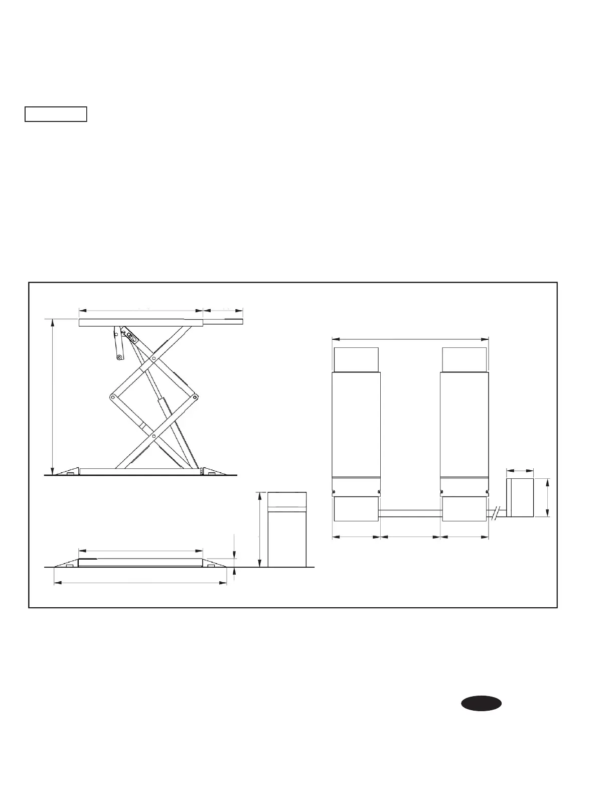
EasyManuals Logo

Rotary 300 Series Installation Instructions

Rotary 300 Series
24 pages
To Next Page IconTo Next Page
To Previous Page IconTo Previous Page
Page #2 background imageLoading...
Page #2 background image
1. Lift Location:
Use architects plan when available to locate lift. Fig. 1
shows typical lift dimensions. Lift floor area should be
level.
IMPORTANT
Base must be fully supported. It must not
be allowed to flex. Grouting must be done and anchor
bolts must not extrude past the nuts, see page 16.
Console is always closest to P1. P1 may be placed on
the left or right. Switch extensions as necessary so that
extension handle faces the outside of lift.
Fig. 1
1525
2002/2052
750/800626
450
626
1525
2167
1920
1080
125
450
490
2

Other manuals for Rotary 300 Series

Questions and Answers:

Question and Answer IconNeed help?

Do you have a question about the Rotary 300 Series and is the answer not in the manual?

Rotary 300 Series Specifications

General IconGeneral
BrandRotary
Model300 Series
CategoryScissor Lifts
LanguageEnglish

Related product manuals