Operating Manual - NK 100
[en] 09/2008 3.1
3 Technical Description
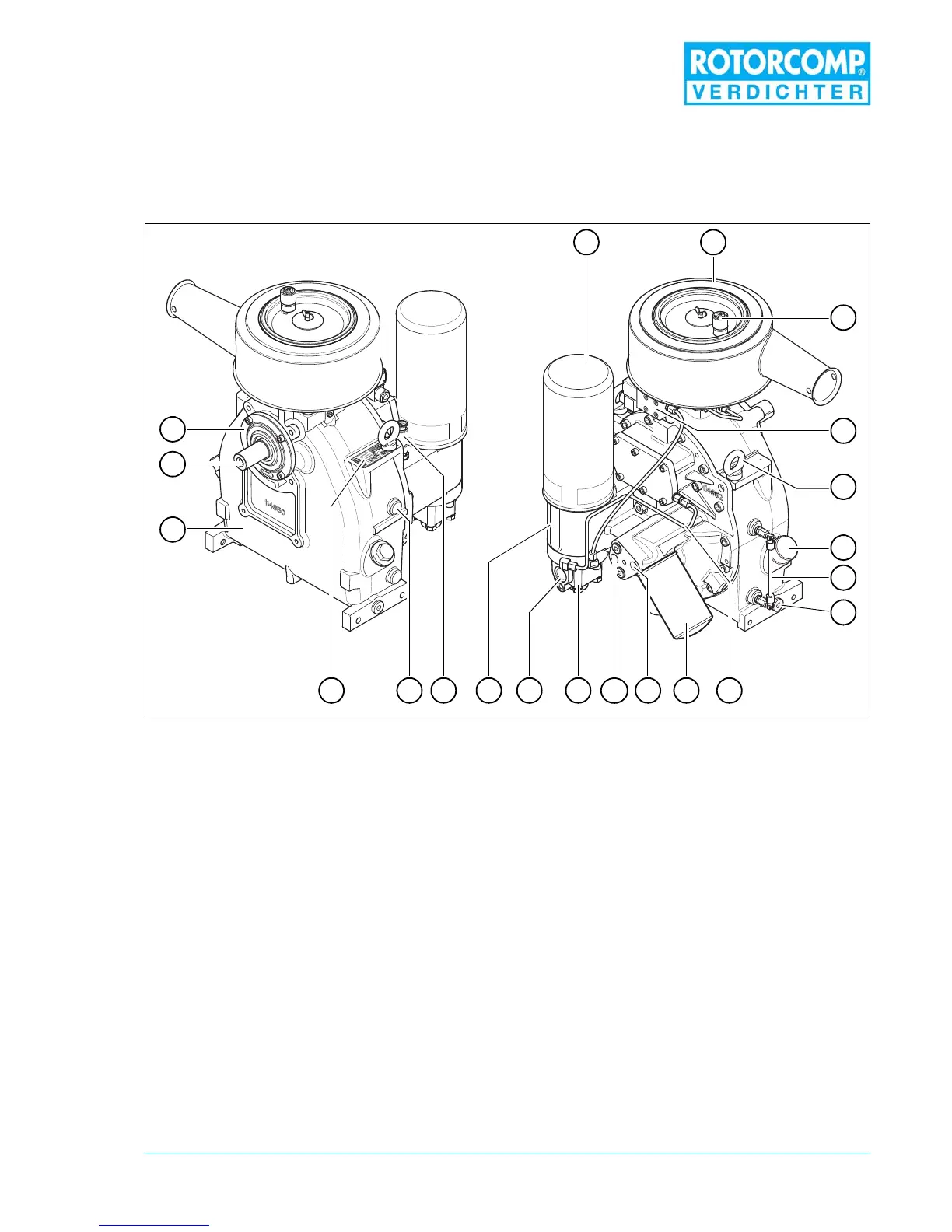
3.1 General overview of NK 100 Screw Compressor Compact Module
(standard model with electric control unit)
Figure 3-1
1. Air-oil separating element
2. Intake valve with air filter
3. Maintenance indicator for intake filter (optional)
4. Control unit, electric
5. Transport eye
6. Oil filler opening
7. Oil level monitoring (optional)
8. Oil drain screw
9. Oil separation return line with oil-extraction sight glass (optional)
10. Oil filter
11. Oil circulation/On
12. Oil circulation/Off
13. Minimum pressure valve
14. Compressed air outlet
15. Separator head
16. Safety valve (optional)
17. Temperature sensor connection (optional)
18. Nameplate
19. NK 100 basic module
20. Drive shaft
21. End cover
3
8
6
7
20
19
21
21
5
1011121318 1415 917 16
4
 Loading...