ROTRONIC AG, CH-8303 Bassersdorf
Tel. +41 44 838 11 44, www.rotronic.com
ROTRONIC Messgeräte GmbH, D-76275 Ettlingen
Tel. +49 7243 383 250, www.rotronic.de
ROTRONIC SARL, 56, F - 77183 Croissy Beaubourg
Tél. +33 1 60 95 07 10, www.rotronic.fr
ROTRONIC Italia srl, I- 20157 Milano
Tel. +39 2 39 00 71 90, www.rotronic.it
ROTRONIC Instruments (UK) Ltd, West Sussex RH10 9EE
Phone +44 1293 571000, www.rotronic.co.uk
ROTRONIC Instrument Corp, NY 11788, USA
Phone +1 631 427-3898, www.rotronic-usa.com
ROTRONIC Instruments Pte Ltd, Singapore 159836
Phone +65 6376 2107 www.rotronic.sg
ROTRONIC Shanghai Rep. Offi ce, Shanghai 200233, China
Phone +86 40 08162018, www.rotronic.cn
V+
GND
GND
OUT1
OUT2
=
~
V+
GND
GND
OUT1
OUT2
86
86
Programming
The basic settings of the devices are made in the factory according to your order. The trans-
mitters are adjusted in the factory and therefore do not need to be checked and readjusted
during installation. The devices can be started immediately after installation.
Using HW4 or SW21 software and a standard mini USB cable, the following operations may
be performed.
• Rescaling of the analog outputs
• Single point adjustment
• General settings
Procedure
• Connect the device to the supply voltage
• Connect the device with your PC using the mini-USB cable
• Program the device using HW4 or SW21 software
• Disconnect the device from power for at least two seconds in order to validate the new setting
Sources of error
Measured values can be infl uenced by the following factors:
Temperature errors
Equilibration time too short, cold outside wall, heating elements, sunlight, etc.
Humidity errors
Steam, water spray, dripping water or condensation at the sensor, etc.
Soiling:
By dust in the air. The choice of probe fi lter depends on the amount of soiling at the measuring
point. The fi lter must be cleaned or replaced periodically.
Periodic calibration of the transmitter
The humidity and temperature sensor including the corresponding electronics are very
stable and do not normally need to be changed or calibrated after factory calibration. The
long term stability of the ROTRONIC Hygromer humidity probes is typically better than 1 %RH
per year. For maximum accuracy we recommend calibration of the probe about every six to
12 months. More frequent calibration can be necessary in applications where the sensor is
exposed to pollutants. The calibration can be performed by the user himself on site or in the
laboratory / workshop. For routine calibrations the probe should be checked at one or two
points. The electronics of the transmitter do not normally require calibration in the fi eld.
The electronics cannot be repaired in the fi eld and should be returned to the manufacturer
in the case of problems.
Technical data (operation)
Temperature -20...50 °C
Humidity 0...100 %RH, non-condensing
Accuracy %RH (10…90 %RH) <3 % RH
Accuracy °C (0…50 °C) <0.3 °C
Temperature and humidity analogue output scaling
Humidity 0…100 %RH
Temperature Depends on the order code
Outputs Current or voltage signals, service interface
A
Mechanical installation
Caution:
In order to get correct measurement values, the sensor must be instaled in a way
that the air fl ows around the transmitter.
1. Remove the montage plate by drilling out the screws.
2. Mount the mounting plate to the wall by using 2 screws.
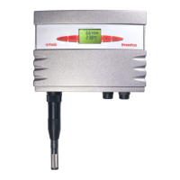
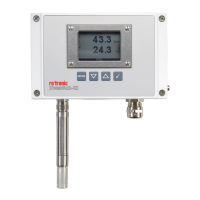
Type L
Type S
Terminal confi guration / Connection diagrams
The type is defi ned using the table «Supply voltage / Technology» to then use the following
connection diagrams:
2- or 2x2-wire / HF120
Terminal Schematics Description
1 V
+ Supply voltage +
2 T– OUT Analogue temperature output
3 V+ Supply voltage +
4 H– OUT Analogue humidity output
3 / 4-wire circuit / HF13x
Terminal Schematics Description
1 V+ Supply voltage +/Phase
2 GND GND / Neutral
3 OUT1 Analogue humidity output +
4 OUT2 Analogue temperature output +
Current output
Voltage output
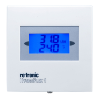
Digital transmitter for humidity & temperature:
Space version
SHORT INSTRUCTION MANUAL
A
Electrical installation
Caution:
Wrong supply voltages and excessively high loading of the outputs can
damage the transmitter.
Supply voltage / Technology
Type Supply voltage V+ Load Output
2- or 2x2 wire
HF120 10...28 VDC: 10 V + (0.02 x load) Max 500 Ω 4...20 mA
3/4 wire
HF132 15...40 VDC / 12... 28 VAC Max 500 Ω 4...20 mA
HF133 15...40 VDC / 12... 28 VAC Max 500 Ω 0...1 V
HF134 15...40 VDC / 12... 28 VAC Max 500 Ω 0...5 V
HF135 15...40 VDC / 12... 28 VAC Max 500 Ω 0...10 V
Congratulations on your purchase of the HygroFlex1-Series transmitter.
Please read these short instructions carefully before installing the device.
General description
The HygroFlex1-Series devices are universal transmitters for transmission of humidity and
(or) temperature measurements. Additional information can be found on the internet at:
www.rotronic.com
Dimensions / connections