Page 3 of 9
INSTALLATION
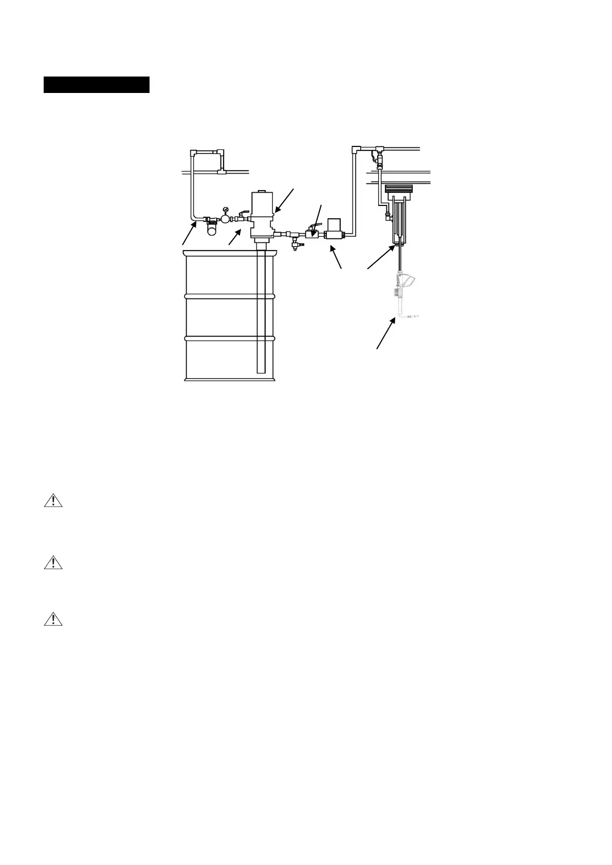
Typical installation refers to Fig.1 (typical installation).
1 Air inlet
2 Air shut-off valve
3 Oil pump 4 Fluid shut-off valve
5 Meter
6 Hose reel
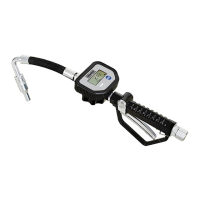
7 Control valve
NOTE: The above typical installation is only for reference. It may be different from your actual system design.
WARNING: If this is a new installation, or if the oil in the lines is contaminated, flush the lines before you
install the control valve.
1. PRE-INSTALLATION PROCESS
WARNING: To reduce the risk of serious injury, pay attention to the pressure release. Follow the Pressure
Relief Procedure in the OPERATION INSTRUCTIONS section for the release process.
(1) Close the fluid shut-off valve 4 as shown in Fig. 1.
(2) Ground the hose and reel or console.
WARNING: To reduce the risk of static sparking, effectively ground all equipment.
⚫ Control valve: Use proper grounding wire to connect it to the pump. Always keep the metal part of the
control valve connected with the grounding equipment.
⚫ Pump: Follow the manufacturer's instructions for grounding.
⚫ Air and fluid hoses: Make sure they are effectively grounded.
⚫ Air compressor: Follow the manufacturer's instruction to ground it.
⚫ Oil barrel: Use a barrel that meets the local standard and ground it properly. A metal barrel can be put
directly on a surface of an electrical conductor which is well grounded.
⚫ Staying grounded during the working and oil release process: Make sure that the metal units are
effectively grounded before operating the control valve.