8 Section 3 — ASSembly & Set-Up
Figure 3-6
3. Secure chipper chute with the three cupped washers (a)
(cupped side against the chipper chute) and hex nuts (b)
removed in Step 1. See Figure 3-6 inset. Tighten the nuts at
this time.
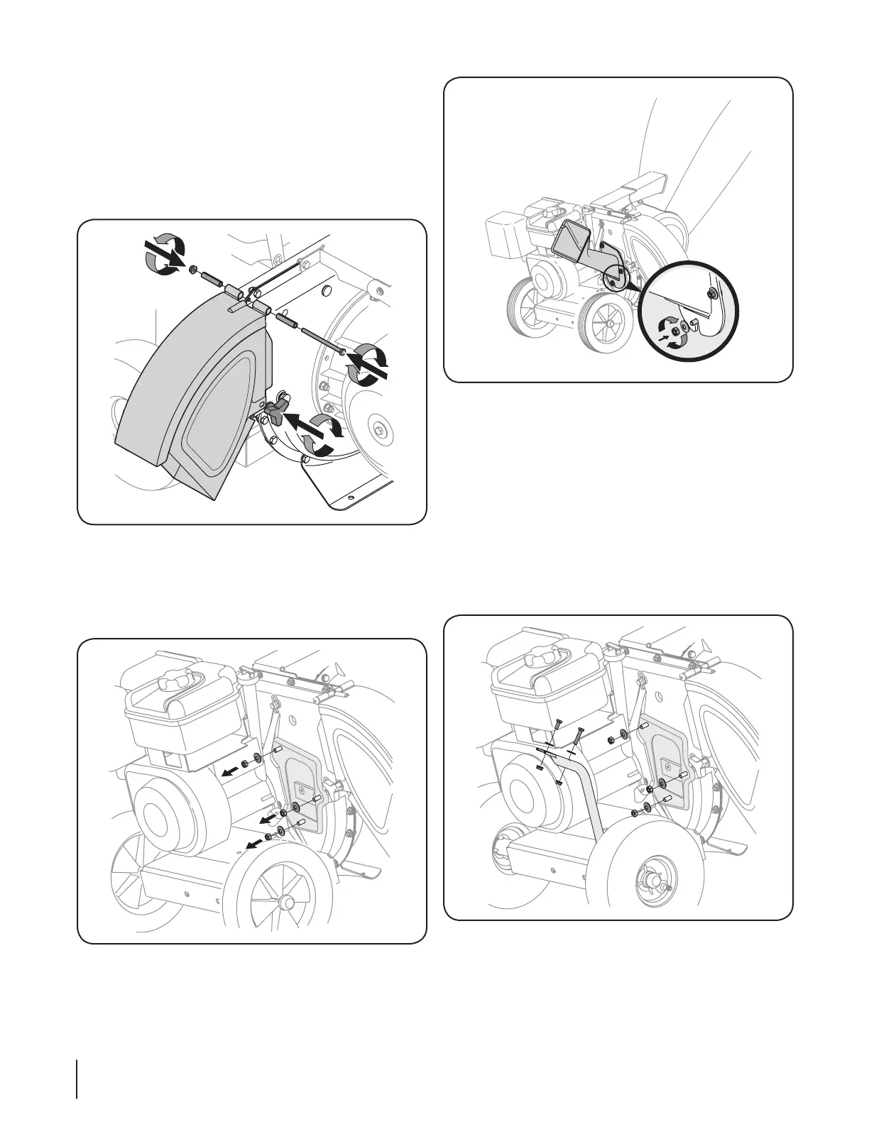
Chipper Chute (Model Series 460)
1. Remove the three cupped washers (a) and hex nuts (b)
from weld studs around the opening on the side of the
impeller housing. See Figure 3-7.
2. Remove the hex bolts (c), flat washers (d), and lock nuts (e)
from the two holes on the upper end of the support brace.
See Figure 3-7.
(a)
(b)
(b)
(a)
(a)
(c)
(e)
(e)
(c)
(b)
(d)
(d)
Figure 3-7
3. Align the chute deflector in position on the discharge
opening and insert hex bolt (d) with spacer (c) through
hinge on chute deflector (spacers fit inside of hinges).
See Figure 3-4.
4. Place second spacer (c) over hex bolt (d) inside other hinge
and secure with hex lock nut (b). See Figure 3-4.
5. Secure both sides of chute deflector to impeller housing
using wing knobs (a) removed in Step 1. See Figure 3-4.
Figure 3-4
Chipper Chute (Model Series 450)
1. Remove the three cupped washers (a) and hex nuts (b)
from weld studs around the opening on the side of the
impeller housing. See Figure 3-5.
Figure 3-5
2. Align the chipper chute over the weld studs, so the slot in
the bottom of the chute is facing down. See Figure 3-6.