plenum chamber to the inlet manifold (see
illustration).
41 Lift the plenum chamber off the manifold,
and recover the four locating sleeves and O-
ring seals.
42 Clean the manifold and plenum chamber
mating faces, and renew the O-ring seals if
they show any sign of deterioration.
Refitting
43 Refitting is a reversal of removal. Fit the
locating sleeves to the manifold before the O-
ring seals, and tighten all nuts and bolts
securely.
Fuel pressure regulator
Removal
44 Disconnect the battery negative (earth)
lead (refer to Chapter 5, Section 1).
45 Relieve the fuel system pressure as
described in Section 5.
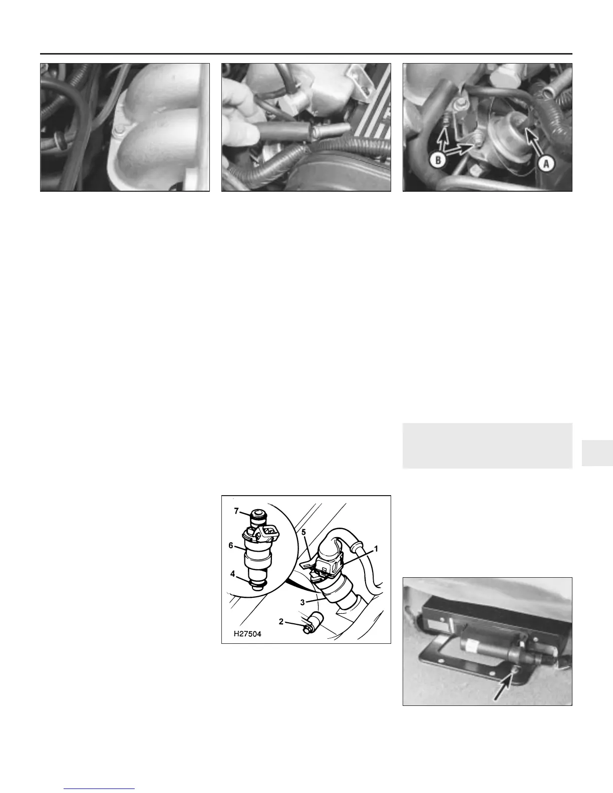
46 Detach the breather hose from the
camshaft cover, and move the hose aside
(see illustration).
47 Disconnect the vacuum hose from the top
of the regulator (see illustration).
48 Unscrew the fuel return hose union from
the base of the regulator.
49 Undo the regulator bracket retaining
bolts, and withdraw the regulator from the fuel
rail.
Refitting
50 Refitting is a reversal of removal.
Fuel injectors
Removal
51 Disconnect the battery negative (earth)
lead (refer to Chapter 5, Section 1).
52 Relieve the fuel system pressure as
described in Section 5.
53 Remove the plenum chamber and fuel
temperature switch as described previously.
54 Detach the breather hose from the
camshaft cover, and move the hose aside.
55 Disconnect the fuel pressure regulator
vacuum hose.
56 Undo the fuel pressure regulator
mounting bracket bolts.
57 Undo the union nut, and disconnect the
fuel supply hose from the fuel rail.
58 Undo the union nut, and disconnect the
fuel return hose from the fuel pressure
regulator.
59 Disconnect the multiplugs from each of
the four injectors (see illustration).
60 Undo the two bolts securing the fuel rail to
the inlet manifold.
61 Ease the four injectors out of their inlet
manifold locations, and lift up the injector and
fuel rail assembly. Recover the O-ring seal
from each injector outlet.
62 Extract the retaining clips, and remove the
injectors from the fuel rail. Recover the O-ring
seal from each injector inlet.
Refitting
63 Refitting is a reversal of removal, but
renew the injector inlet and outlet O-rings.
Electronic control unit (ECU)
Removal
64 Disconnect the battery negative (earth)
lead (refer to Chapter 5, Section 1).
65 Slide the driver’s seat fully forwards.
66 From under the driver’s seat, undo the
two screws and lift off the ECU cover.
67 Undo the bolt securing the rear of the
mounting bracket to the floor (see
illustration).
68 Slide the driver’s seat fully rearwards, and
undo the two bolts securing the front of the
mounting bracket to the floor.
69 Withdraw the ECU and mounting bracket
assembly from under the seat.
70 Depress the multiplug retaining tab, and
pull the plug straight from the socket.
71 Remove the ECU from the car.
Refitting
72 Refitting is a reversal of removal.
Resonator unit
Refer to Part A, Section 12.
Inertia switch
Refer to Part A, Section 12.
13 Turbocharger - description
and precautions
Description
1 On turbocharged engines, the turbocharger
increases engine efficiency by raising the
pressure in the inlet manifold above
atmospheric pressure. Instead of the air
simply being sucked into the cylinders, it is
forced in.
2 Energy for the operation of the
turbocharger comes from the exhaust gas.
Fuel and exhaust systems - Lucas multi-point injection engines 4B•7
12.47 Fuel pressure regulator vacuum
hose (A) and mounting bracket bolts (B)
12.46 Detach the breather hose from the
camshaft cover
12.40 Plenum chamber to inlet manifold
retaining bolt locations
12.67 ECU mounting bracket retaining bolt
(arrowed)
12.59 Fuel injector and fuel rail details
1 Injector multiplug
2 Fuel rail retaining bolt
3 Fuel injector location on inlet manifold
4 Injector outlet O-ring seal
5 Injector to fuel rail retaining clip
6 Injector body
7 Injector inlet O-ring seal
4B
1380 Rover 800 Series Remake


 To Next Page
 Loading...
