terminals (see illustration). The primary
winding resistance should be as given in the
Specifications at the beginning of this
Chapter. If the resistance is not as specified,
the coil should be renewed.
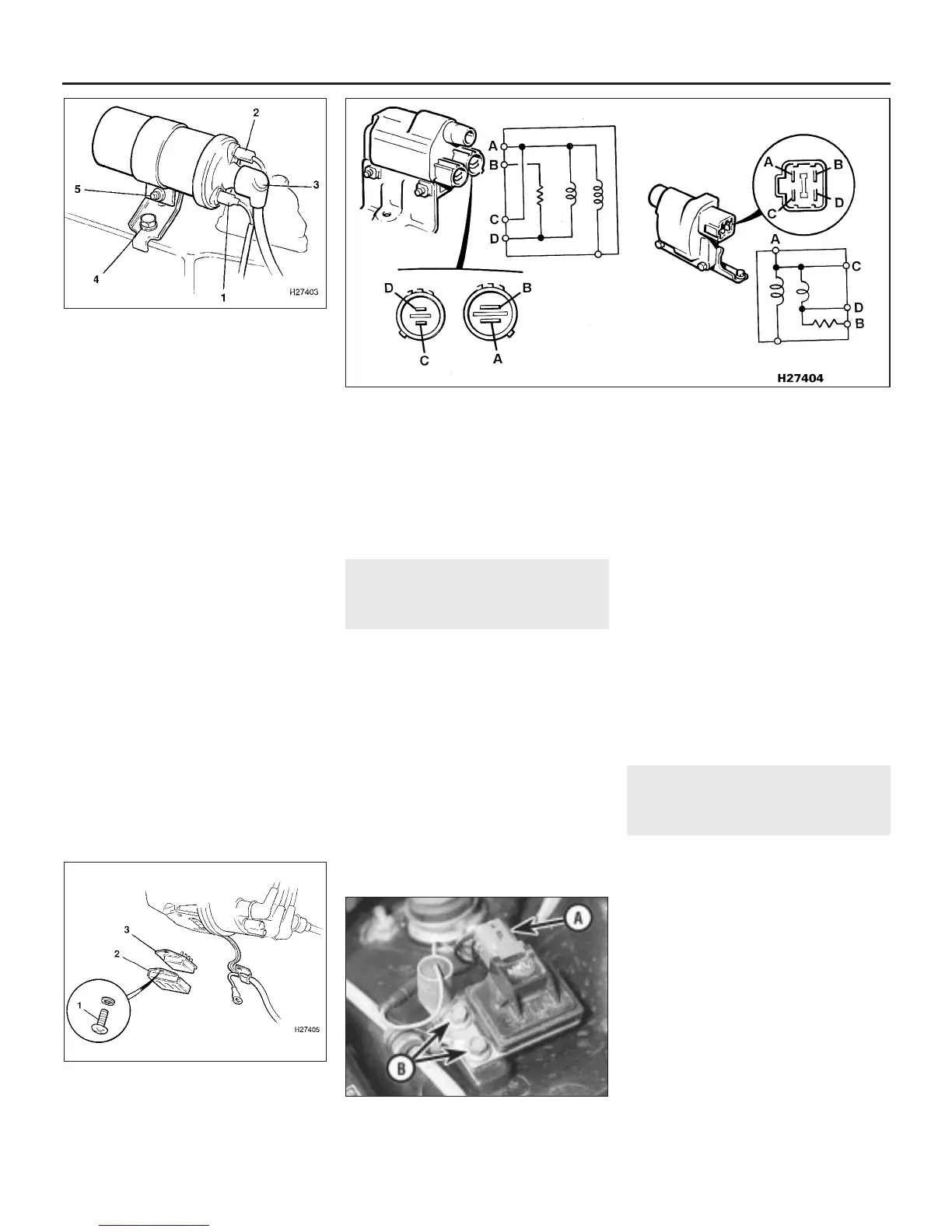
4 On V6 engines, disconnect the wiring
multiplug(s) and the distributor HT lead at the
coil and connect an ohmmeter across the
multiplug terminals as follows (see
illustration).
Between terminals C and D.
Between terminals B and D.
Between terminal A and the HT terminal.
The resistances should be as given in the
Specifications at the beginning of this
Chapter. If the resistance is not as specified,
the coil should be renewed.
5 If the coil is thought to be faulty, have your
findings confirmed by a Rover dealer before
renewing the coil.
Removal
6 To remove the coil, disconnect the LT leads
or multiplugs at the coil terminals, and the HT
lead at the centre terminal.
7 Undo the mounting bracket retaining bolt(s)
and remove the coil.
8 On 4-cylinder engines, note the position of
the positive and negative terminals in relation
to the mounting bracket, then slacken the
mounting bracket screw and slide out the coil.
Refitting
9 Refitting is a reversal of removal.
8 Igniter (V6 engines) -
removal and refitting
3
2.5 litre engines
Removal
1 Remove the distributor as described in
Section 6.
2 Undo the two igniter cover securing screws
on the side of the distributor body (see
illustration).
3 Move the wiring aside and lift off the cover.
4 Carefully withdraw the igniter from its
connection on the side of the distributor.
Refitting
5 Thoroughly clean the mating faces of the
igniter and distributor and apply a silicone
grease to the distributor mating face.
6 Locate the igniter in position then refit the
cover and the wiring clip.
7 Refit the distributor as described in Sec-
tion 6, then adjust the ignition timing as
described in Section 10.
2.7 litre engines
Removal
8 The igniter is located on the left-hand side
of the engine compartment, behind the
fusebox (see illustration).
9 Ensure that the ignition is switched off then
disconnect the igniter wiring multiplug.
10 Undo the two retaining screws and
withdraw the igniter from its mounting
bracket.
Refitting
11 Refitting is a reversal of removal.
9 Ignition timing
sensor/adjuster (V6 engines)
- removal and refitting
3
General
1 The ignition timing sensor/adjuster is only
fitted to 2.7 litre engines and is located in the
control box mounted on the engine
compartment bulkhead. On non-catalyst
equipped engines, the ignition timing adjuster
is used to alter the ignition timing to allow the
engine to run on leaded or unleaded fuel. On
catalyst equipped engines the ignition timing
is not adjustable and the ignition timing
sensor is used in a monitoring capacity by the
fuel system ECU.
Removal
2 Disconnect the battery negative (earth) lead
(refer to Section 1 before doing this).
3 Slacken the two bolts securing the control
box to the bulkhead.
5•6 Engine electrical systems
8.8 Igniter multiplug (A) and retaining
screws (B) on 2.7 litre engines
8.2 Igniter component details on 2.5 litre
engines
1 Retaining screws 3 Igniter
2 Igniter cover
7.4 Ignition coil connections and terminal identification on V6 engines
Left-hand illustration - manual transmission Right-hand illustration - automatic transmission
7.3 Ignition coil connections and
attachments on 4-cylinder engines
1 LT negative lead
2 LT positive lead
3 HT lead
4 Mounting bracket retaining bolt
5 Coil-to-bracket retaining screw
1380 Rover 800 Series Remake


 To Next Page
 Loading...
