3 Support the steering knuckle in a wide-
opening vice or on a press bed, and using
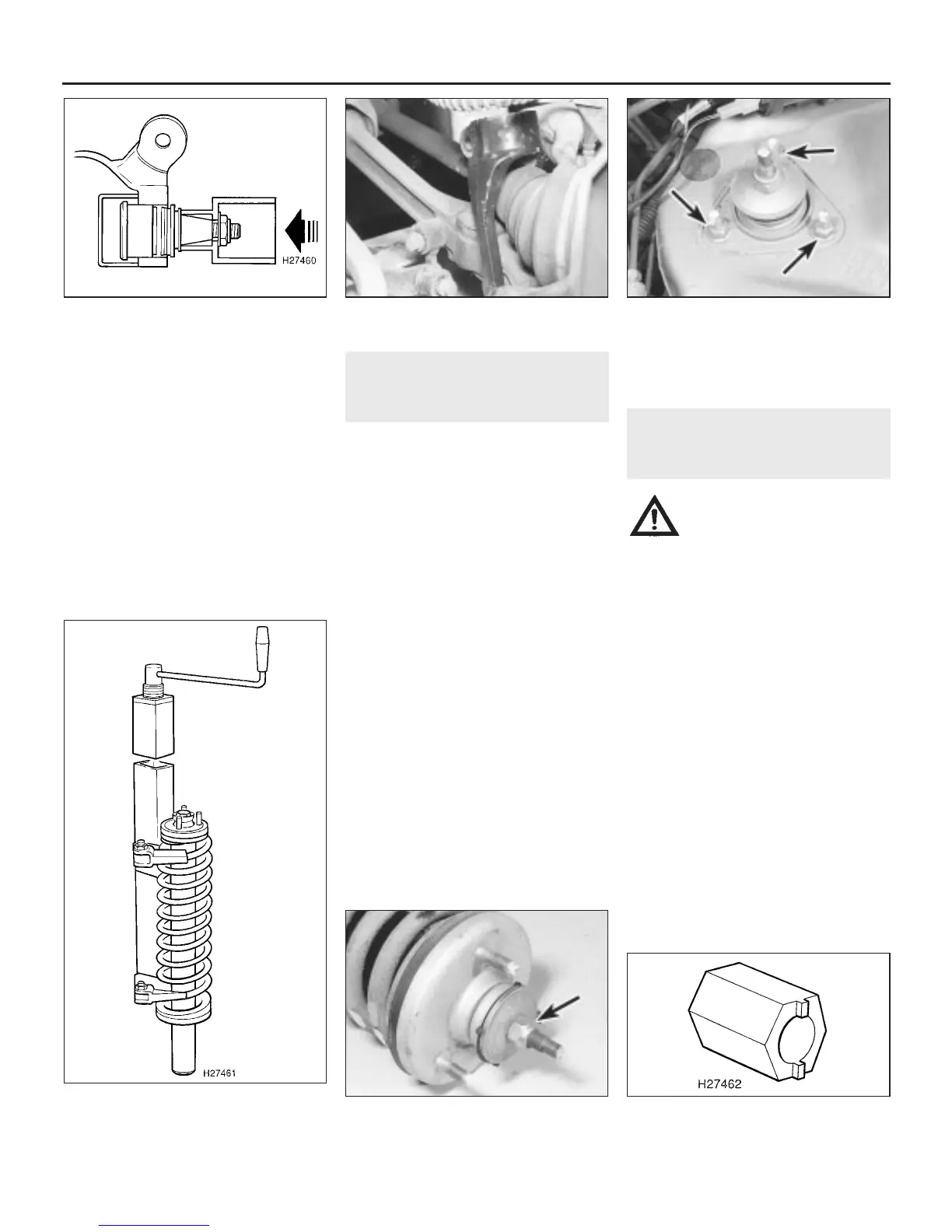
tubes as mandrels and distance pieces, press
the balljoint out of the knuckle. The
manufacturer’s special tools being used for
this purpose are shown, to give an idea of the
arrangement, but lengths of tubular steel work
equally well (see illustration).
Refitting
4 Using the same basic procedure as for
removal, fit the new balljoint until its shoulder
contacts the steering knuckle flange.
5 Fit the new dust cover and secure the
assembly with the circlip.
6 Refit the steering knuckle to the car as
described in Section 2.
5 Front shock absorber and
coil spring assembly -
removal and refitting
3
Removal
1 Apply the handbrake, prise off the front
wheel trim and slacken the wheel nuts. Jack
up the front of the car and support it on axle
stands. Remove the front roadwheel.
2 Place a jack beneath the lower suspension
arm and raise the arm slightly.
3 Undo the nut and remove the through-bolt
securing the forked member to the lower
suspension arm.
4 Undo the nut and remove the clamp bolt
securing the forked member to the shock
absorber.
5 Slowly lower the jack, and remove the
forked member from the shock absorber and
lower suspension arm (see illustration). It
may be necessary to tap the member down
using a copper or plastic mallet to release it
from the shock absorber.
6 Have an assistant hold the assembly, from
below, then undo the three nuts securing the
shock absorber top mounting to the body
turret in the engine compartment (see
illustration).
7 Remove the shock absorber and spring
assembly from under the wheelarch.
Refitting
8 Refitting is a reversal of removal. Tighten all
nuts and bolts to the specified torque, but do
not fully tighten the forked member-to-lower
arm bolt and nut until the weight of the car is
on the roadwheels.
6 Front shock absorber and
coil spring assembly -
dismantling and reassembly
4
Warning: Before attempting to
dismantle the shock absorber
and coil spring assembly, a tool
to hold the spring in
compression must be obtained. Adjustable
coil spring compressors are readily
available, and are recommended for this
operation. Any attempt at dismantling
without such a tool is likely to result in
damage or personal injury.
Dismantling
1 Remove the shock absorber and coil spring
assembly as described in the previous
Section.
2 Position the spring compressors on either
side of the spring, and compress the spring
evenly until there is no tension on the spring
seat or upper mounting (see illustration).
3 Hold the unthreaded end of the shock
absorber spindle with a self-locking wrench or
similar tool, and unscrew the upper mounting
retaining nut (see illustration).
4 Withdraw the washer under the nut,
followed by the upper bush, the upper
mounting plate and the spring seat.
5 To remove the threaded collar on the shock
absorber spindle, it will be necessary to make
up a tool which will engage in the slots on the
collar, enabling it to be unscrewed. A tool can
10•6 Suspension and steering systems
6.3 Remove the retaining nut (arrowed)
from the shock absorber spindle
5.6 Shock absorber top mounting
retaining nuts (arrowed)
5.5 Removing the front suspension forked
member
4.3 Rover special tool for steering knuckle
balljoint removal
1380 Rover 800 Series Remake
6.2 Coil spring and shock absorber
assembly, showing spring compressor tool
in position
6.5 Shock absorber threaded collar home-
made removal tool


 To Next Page
 Loading...
