7 Insert the balljoint into the steering knuckle
arm and refit the retaining nut. Tighten the nut
to the specified torque, then tighten it further,
slightly, to align the next split pin hole. Secure
the nut with a new split pin.
8 Tighten the track rod retaining locknut
securely, refit the roadwheel and lower the car
to the ground. Tighten the wheel nuts and refit
the wheel trim.
9 Check the front wheel alignment as
described in Section 28.
23 Steering gear rubber gaiter -
renewal
4
Removal
1 Remove the steering track rod as described
in the previous Section.
2 Count and record the number of exposed
threads from the end of the inner track rod to the
locknut, then unscrew and remove the locknut.
3 Release the rubber gaiter retaining clips,
remove the transfer tube (V6 engine models)
and withdraw the gaiter from the steering gear
and inner track rod.
Refitting
4 Slide the new gaiter into position and
secure it with new retaining clips. Where
applicable, refit the transfer tube.
5 Refit the locknut to the inner track rod, and
position it so that the same number of threads
are exposed as counted on removal.
6 Refit the steering track rod as described in
the previous Section.
24 Steering gear -
removal and refitting
4
4-cylinder engine models
Removal
1 From inside the car, release the two
retaining clips and slide up the cover over the
universal joint at the base of the steering
column (see illustration 21.6).
2 Move the carpets aside to gain access to
the floor-mounted cover plate.
3 Prise out the retaining studs to release the
cover plate and gasket from the floor.
4 Undo the clamp bolt securing the universal
joint to the steering gear pinion.
5 Apply the handbrake, remove the front
wheel trims and slacken the wheel nuts. Jack
up the front of the car and support it on axle
stands. Remove the front roadwheels.
6 Remove the exhaust front pipes as
described in the relevant Part of Chapter 4.
7 Extract the split pins, then unscrew the nuts
securing each track rod balljoint to the
steering knuckle arm.
8 Using a universal balljoint separator tool,
release the balljoint tapered ball-pins from the
arms.
9 Position a suitable container beneath the
pinion end of the steering gear.
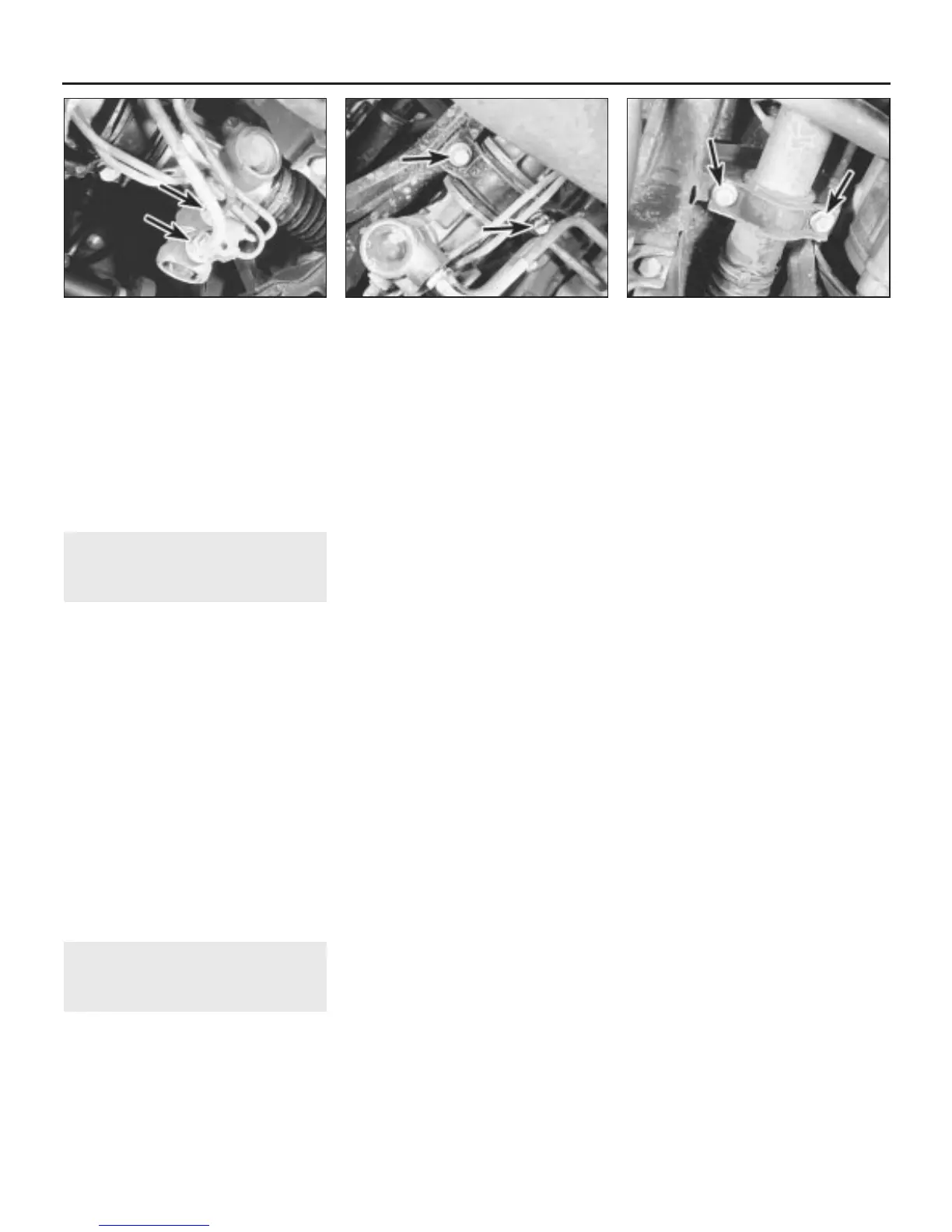
10 Wipe clean the area around the fluid pipe
unions, then unscrew the two rearward-facing
union nuts on the pinion housing (see
illustration). Allow the power steering fluid to
drain into the container.
11 Remove the two O-ring seals from the
disconnected pipes, then plug or tape over
the pipe ends and orifices.
12 Undo the two bolts each side securing the
steering gear to the chassis members, and
remove the mounting brackets (see
illustrations).
13 Lower the steering gear to release the
pinion from the column universal joint, then
manipulate the assembly sideways and out
through the wheelarch.
14 Check the condition of the rubber
mountings, and renew them if there is any
sign of deterioration or swelling of the rubber.
Refitting
15 Refitting the steering gear is a reversal of
removal, bearing in mind the following points:
(a) Tighten all nuts, bolts and unions to the
specified torque.
(b) Use new O-ring seals on the pipe unions,
and new split pins on the balljoint
retaining nuts.
(c) Fill the system with fresh fluid, and bleed the
steering gear as described in Section 25.
(d) If necessary, reposition the steering wheel
so that the spokes are horizontal when the
steering gear is in the straight-ahead
position (see Section 18).
V6 engine models
Removal
16 Proceed as described in paragraphs 1 to
8 above.
17 Undo the bolts securing the longitudinal
support member to the underbody beneath
the engine and remove the member.
18 Engage a spanner over the flats on the
left-hand inner track rod that protrudes from
the rubber gaiter, then unscrew the steering
track rod and outer balljoint assembly.
Remove the right-hand steering track rod in
the same way.
19 Undo the four bolts and remove the cover
plate from below the pinion end of the
steering gear.
20 Position a suitable container beneath the
steering gear fluid pipes.
21 Wipe clean the area around the fluid pipe
unions, then unscrew the four union nuts on
the pinion housing. Allow the power steering
fluid to drain into the container.
22 Plug or tape over the disconnected pipe
ends and orifices to prevent dirt entry.
23 Undo the two bolts each side securing the
steering gear to the chassis members, and
remove the mounting brackets.
24 Lower the steering gear to release the
pinion from the column universal joint, then
manipulate the assembly sideways and out
through the wheelarch.
25 Check the condition of the rubber
mountings, and renew them if there is any
sign of deterioration or swelling of the rubber.
Refitting
26 Refitting the steering gear is a reversal of
removal, bearing in mind the following points:
(a) Tighten all nuts, bolts and unions to the
specified torque.
(b) Use new split pins on the balljoint
retaining nuts.
(c) Fill the system with fresh fluid, and bleed the
steering gear as described in Section 25.
(d) If necessary, reposition the steering wheel
so that the spokes are horizontal when the
steering gear is in the straight-ahead
position (see Section 18).
10•16 Suspension and steering systems
24.12b . . . and left-hand mounting bracket
bolts (arrowed)
24.12a Steering gear right-hand mounting
bracket bolts (arrowed) . . .
24.10 Unscrew the two fluid pipe union
nuts (arrowed)
1380 Rover 800 Series Remake


 To Next Page
 Loading...
