connection being tested. The resistance
reading should be zero; if not, check the
connection as follows.
22 If an earth connection is thought to be faulty,
dismantle the connection, and clean both the
bodyshell and the wire terminal (or the
component earth connection mating surface)
back to bare metal. Be careful to remove all
traces of dirt and corrosion, then use a knife to
trim away any paint, so that a clean metal-to-
metal joint is made. On reassembly, tighten the
joint fasteners securely; if a wire terminal is being
refitted, use serrated washers between the
terminal and the bodyshell, to ensure a clean
and secure connection. When the connection is
remade, prevent the onset of corrosion in the
future by applying a coat of petroleum jelly or
silicone-based grease, or by spraying on (at
regular intervals) a proprietary ignition sealer.
3 Fuses and relays -
general information
1
Note: It is important to note that the ignition
switch and the appropriate electrical circuit must
always be switched off before any of the fuses (or
relays) are removed and renewed. In the event of
the fuse/relay unit having to be removed. When
disconnecting the battery, reference should be
made to Chapter 5, Section 1.
General
1 Two or three fuseboxes are used on Rover
800 models. One is located inside the car
under the facia on the driver’s side with an
auxiliary fusebox alongside it, another is
located on the left-hand side of the engine
compartment and, on later models, a third is
located in the luggage compartment on the
left-hand side. The main vehicle system relays
are located on a relay panel behind the interior
fusebox, and also in the engine compartment
fuse and relay box. Additional relays are
located in various locations according to
model and equipment fitted.
Interior fusebox
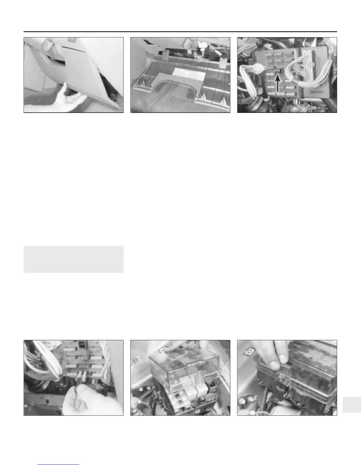
2 To gain access to the fuses, release the
turnbuckles at the base of the trim panel
beneath the steering column, and lift away the
panel. The fuse locations, current rating and
circuits protected are shown on a label
attached to the inside of the panel. Each fuse
is also colour-coded, and has its rating
stamped on it (see illustrations).
3 To remove a fuse from its location, withdraw
the removal tool from the fusebox, push the
tool over the fuse to be removed and pull out
the fuse (see illustrations). Refit the fuse by
pressing it firmly into position. Spare fuses are
located in a vertical row on the right-hand side
of the fusebox, or in marked vacant spaces.
4 Always renew the fuse with one of an
identical rating. Never renew a fuse more than
once without finding the source of the trouble.
5 To gain access to the relays behind the
fusebox, undo the two fusebox retaining
bolts, one at each end, and ease the unit
away from its location. For greater access,
mark the various wiring multiplugs to avoid
confusion when refitting, then disconnect
them and remove the fusebox completely.
6 The relays can be removed by simply
pulling them from their respective locations. If
a system controlled by a relay becomes
inoperative, and the relay is suspect, operate
the system and if the relay is functioning it
should be possible to hear it click as it is
energised. If this is the case, the fault lies with
the components of the system. If the relay is
not being energised, then the relay is either
not receiving a main supply voltage, a
switching voltage, or the relay itself is faulty.
Engine compartment fuse and
relay box
7 The engine compartment fuse and relay
box contains additional fuses, some vehicle
system relays, and the main wiring loom
fusible links.
8 To gain access, press the upper edge of the
retaining catch on the fuse and relay box
cover, lift the cover at the front and disengage
the rear tags (see illustration). A symbol
identifying the function of each fuse is marked
on the cover.
9 The fuses and relays can be renewed in the
same way as for the interior fusebox
described previously. The fuse removal tool,
together with the spare fuses, is located at the
front of the box. On certain models, additional
fuses and relays are located on the outside
edge of the box, with the fuses under a
protective cover. Lift off the cover to renew
each individual fuse (see illustration).
Body electrical system 12•3
3.3a Use the fuse removal tool
(arrowed) . . .
3.2b . . . noting the fuse identification on
the rear of the panel
3.2a Lift away the trim panel for access to
the fusebox . . .
3.9 Additional fuse located under a cover
on the outside of the fuse and relay box
3.8 Removing the engine compartment
fuse and relay box cover
3.3b . . . to withdraw the fuses from their
locations
12
1380 Rover 800 Series Remake


 To Next Page
 Loading...
