8 Disconnect the remaining vacuum hose at
the inlet manifold.
9 Undo the bolt securing the engine rear tie-
bar support bracket to the inlet manifold (see
illustration).
10 Undo the two through-bolts securing the
engine rear tie-bar to the engine and body
brackets, and recover the special forked nut
(see illustration). Note that the forked end of
the nut engages with a bracket projection to
prevent the nut turning.
11 Withdraw the rear tie-bar from its
brackets, noting that it is stamped with the
word TOP on the upper face of the larger end,
which must be refitted accordingly.
12 Slacken the clips and disconnect the
radiator bottom hose at the radiator and main
coolant pipe, the bottom hose take-off at the
expansion tank pipe, the two heater hoses at
the heater matrix, and the heater outlet hose
at the inlet manifold or throttle housing (see
illustrations). On automatic transmission
models, disconnect the two coolant hoses at
the transmission oil cooler.
13 Place absorbent rags around the fuel filter
outlet banjo union bolt on the left-hand side of
the filter, then slowly unscrew the bleed screw
in the centre of the bolt, or the bolt itself as
applicable, to relieve the fuel system pressure.
When the pressure is released, remove the
bolt and recover the two copper washers.
Tighten the bleed screw where fitted.
14 Release the clip and disconnect the fuel
return hose from the pipe below the fuel filter.
Plug or tape over the disconnected fuel hoses
and unions.
15 Disconnect the accelerator cable at the
throttle end, as described in the relevant Part
of Chapter 4.
16 Undo the brake servo vacuum hose banjo
union bolt at the inlet manifold, and recover
the two copper washers.
17 On cars with single-point fuel injection,
disconnect the wiring multiplug from the
ignition/fuel ECU, and remove the relay from
its holder behind the ECU location (see
illustration).
18 Separate the engine wiring harness from
the main wiring harness by disconnecting the
large round wiring multiplug located behind
the battery. Additionally, on cars with single-
point fuel injection, disconnect the adjacent
large flat multiplug, and on cars with multi-
point fuel injection, the multiplugs at the rear
right-hand side of the engine compartment
(see illustrations).
19 Disconnect the two sensing leads at the
battery clamps, noting their locations, and
also the main positive lead to the starter
motor at the battery clamp.
20 Remove the cover from the fuse and relay
box on the left-hand side of the engine
compartment, then lift off the cover over the
fusible links.
21 Lift out the engine harness cable retaining
clip, undo the cable retaining screw, and
remove the cable from the fuse and relay box
(see illustrations).
2C•4 Engine removal and general engine overhaul procedures
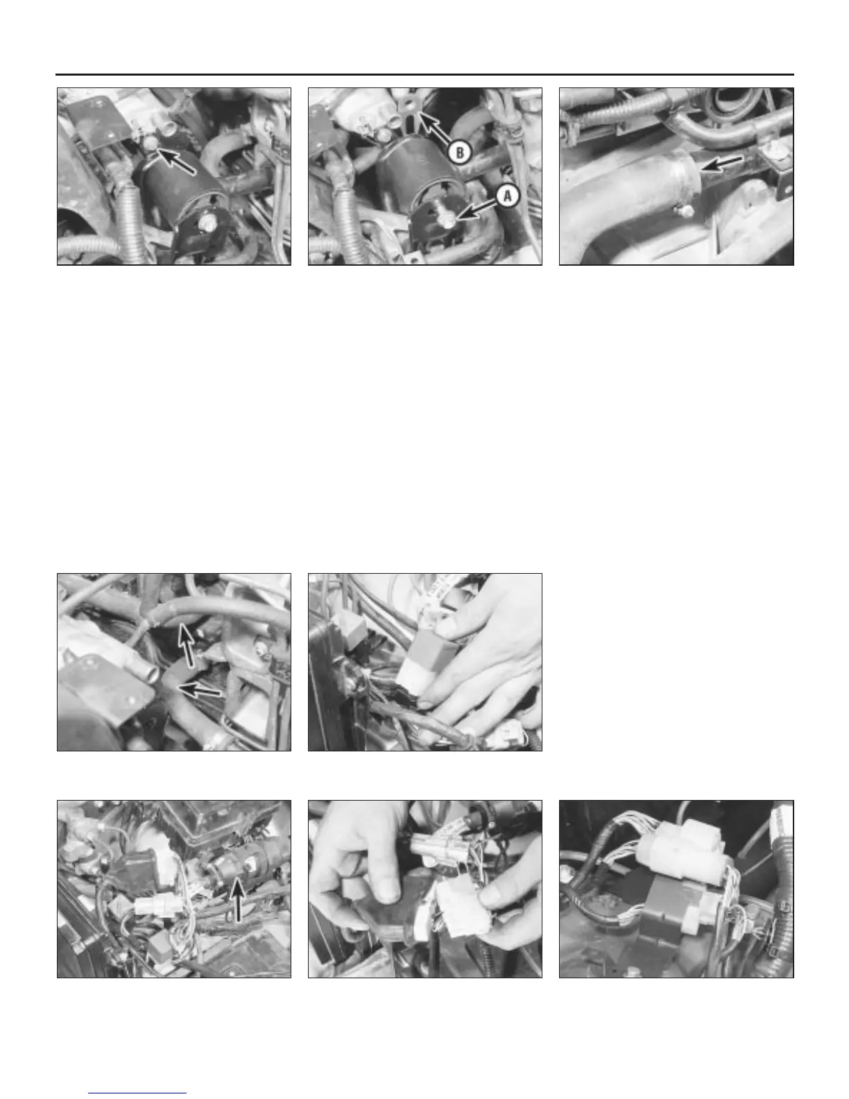
4.18c Disconnect the appropriate multi-
plugs at the rear of the engine compartment
4.18b . . . and the adjacent flat multiplug4.18a Disconnect the large round wiring
multiplug (arrowed) . . .
4.17 Remove the relay behind the
ignition/fuel ECU
4.12b . . . and the heater hoses at the
heater matrix (arrowed)
4.12a Disconnect the radiator hose
(arrowed) at the main coolant pipe . . .
4.10 Remove the tie-bar through-bolt (A)
and recover the forked nut (B)
4.9 Undo the bolt (arrowed) securing the
engine rear tie-bar support bracket to the
inlet manifold
1380 Rover 800 Series Remake
 Loading...