using a flat bar or large screwdriver, lever
between the driveshaft inner constant velocity
joint and the differential housing to release the
joint.
39 Move the driveshaft clear, then repeat
these operations on the left-hand driveshaft.
40 Attach a hoist to the engine using rope
slings, or chains attached to brackets secured
to the cylinder head. Adjust the ropes or
chains so that the engine will hang at
approximately 30º to the horizontal, with the
timing belt end uppermost, when it is lifted
out.
41 On automatic transmission models, undo
the mounting bracket bolts and remove the
engine lower tie-bar from under the front of
the car, complete with mounting brackets.
42 Undo the right-hand engine mounting
through-bolt, and recover the special nut.
Note that the forked end of the nut plate
locates over a stud on the body bracket.
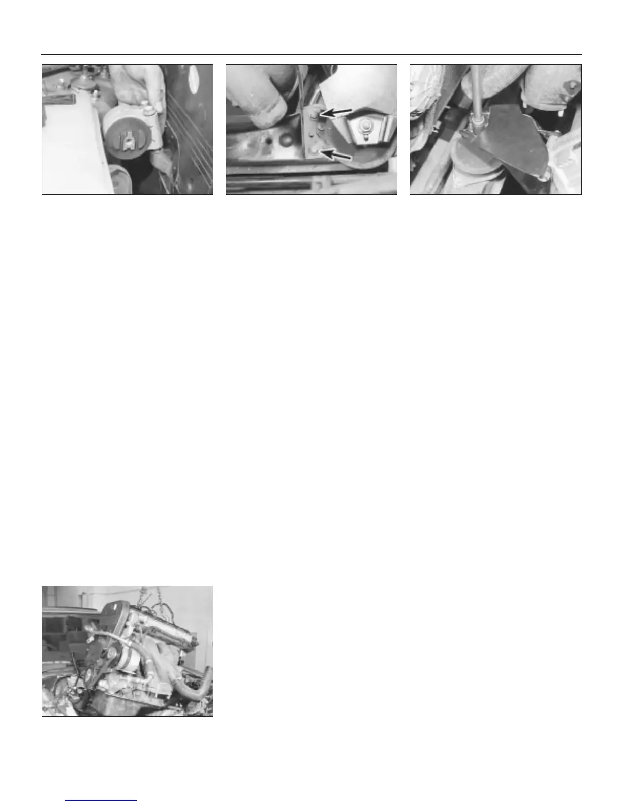
43 Undo the two bolts securing the engine
mounting to its mounting bracket, and remove
the mounting (see illustration).
44 Undo the two bolts securing the air
cleaner trunking support bracket to the front
chassis member, and remove the bracket
(see illustration).
45 Undo the nut securing the front engine
mounting to its transmission bracket (see
illustration).
46 Undo the nut securing the rear engine
mounting to its transmission bracket.
47 Raise the engine slightly, then on cars
with a rear-mounted power steering pump,
undo the power steering pipe union nut at the
rear of the pump, and remove the pipe. Plug
the unions to prevent loss of fluid.
48 Make a final check that everything
connecting the engine and transmission to the
car has been disconnected and moved well
clear.
49 Carefully lift the power unit upwards,
whilst moving and twisting it slightly to clear
the various projections (see illustration).
When the unit has been raised sufficiently,
draw the hoist forwards to bring the engine
unit over the front body panel, then lower it to
the floor.
Separation - manual
transmission models
50 With the engine/transmission removed
from the car, undo the starter motor retaining
bolts, and remove the unit from the clutch
housing.
51 Undo the three bolts and remove the
engine snubber bracket from the transmission
adaptor plate beneath the engine sump.
52 Undo the two bolts securing the front
engine mounting bracket to the transmission,
and remove the bracket.
53 Undo the bolts securing the rear engine
mounting bracket to the transmission, noting
the location of the crankshaft sensor bracket.
Move the sensor aside and remove the
bracket.
54 Undo all the remaining bolts securing the
transmission to the engine.
55 With the transmission well supported,
release the locating dowels and draw the unit
squarely away from the engine.
Separation - automatic
transmission models
56 With the engine/transmission removed
from the car, undo the starter motor retaining
bolts and remove the unit from the converter
housing.
57 Refer to Chapter 7, Part B and release the
kickdown cable from the engine.
58 Turn the crankshaft as necessary, using a
socket or spanner on the crankshaft pulley
bolt, until one of the torque converter retaining
bolts becomes accessible through the starter
motor aperture. Undo the bolt, turn the
crankshaft and remove the remaining two
bolts in the same way.
59 Undo the two bolts securing the front
engine mounting bracket to the transmission,
and remove the bracket.
60 Undo the bolts securing the rear engine
mounting bracket to the transmission, noting
the location of the crankshaft sensor bracket.
Move the sensor aside and remove the
bracket.
61 Undo the remaining bolts securing the
transmission to the engine.
62 With the transmission well supported,
release the locating dowels and draw the unit
squarely away from the engine. Ensure that
the torque converter stays in place on the
transmission.
Attachment - all models
63 Attachment is the straightforward reversal
of the separation sequence, but where
applicable, tighten all nuts and bolts to the
specified torque (Chapter 2, Part A). On
manual transmission models, smear the
gearbox mainshaft and release bearing face
with molybdenum disulphide grease before
attachment.
Refitting
64 Refitting is a straightforward reversal of
removal, bearing in mind the following points:
(a) Refit all the engine mounting bolts
loosely, then tighten them so as not to
place any under strain. Ensure that the
right-hand mounting bolt is positioned
centrally within the elongated slot in the
body bracket.
(b) Refill the cooling system as described in
Chapter 1.
(c) Refill the transmission as described in
Chapter 1.
(d) Fill the engine with oil as described in
Chapter 1.
(e) Refill and bleed the power steering
system as described in Chapter 10.
(f) Adjust the accelerator cable as described
in the relevant Part of Chapter 4, and
where applicable, the automatic
transmission kickdown cable as described
in Chapter 7 Part B.
2C•6 Engine removal and general engine overhaul procedures
4.49 Removing the engine and
transmission from the car
4.45 Undo the nut securing the front
engine mounting
4.44 Undo the bolts (arrowed) and remove
the air cleaner trunking support bracket
4.43 Remove the right-hand engine
mounting
1380 Rover 800 Series Remake
 Loading...