Do you have a question about the Rowe RE3 and is the answer not in the manual?
Instructions for mounting the receiver unit and connecting power and ground wires for operation.
Guidance on replacing the key fob transmitter battery when the indicator LED fails to illuminate.
Procedure to reestablish wireless communication between transmitter and receiver using a magnet.
Details maximum current handling capabilities and protection methods against overloading.
Advises on preventing electrical feedback into inactive RF unit outputs to avoid damage.
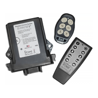
The Rowe Electronics RE3 and RE6 RF System is a wireless control system designed to provide dependable and consistent wireless performance for various applications. These units are virtually maintenance-free, built with quality components for durability, reliability, and a prolonged operational lifespan.
The RE3 and RE6 systems offer a simple and cost-effective solution to the inherent weaknesses of wired control systems. They can be used to drive actuators, open/close gates, drive hydraulic cylinders, open/close valves, and control virtually any application requiring an electrical input. The units feature application-specific firmware programming capabilities, allowing for numerous variants of system behavior such as delayed on/off, system time-out auto-off, momentary or latched output configurations, combined outputs, and RF system on/off control.
For installation, the unit should be mounted in an area that offers as much protection as possible from sources of high heat, moisture, vibration, and electromagnetic interference. While designed to perform effectively in harsh environments, additional protection ensures proper performance and a longer lifespan. It is crucial to mount the receiver unit with the plug facing downward to further protect against corrosion, water damage, and electrical shorts, as the connector is IP rated.
To operate, connect the black ground wire to an effective ground source. Next, connect the red power wire (pin 1) to a main power source (either switched or direct). It is recommended to incorporate a switch into the receiver's main power wire, as the unit draws small amounts of current in stand-by mode, which could discharge a battery if left unattended for long periods. Using a trickle charger or battery tender is also suggested to prevent battery drain. A 7.5 Amp fuse is incorporated into the power lead, and it is critical to NOT replace it with a higher amperage fuse. After connecting the appropriate harness output wires to the device(s), plug the wire harness into the receiver unit. Upon applying power, the red LED on the receiver will flash four times, indicating power-up. The system is then ready for operation. When an active button on the provided transmitter is depressed, both the transmitter's LED and the receiver's LED should illuminate, confirming signal transmission and desired output generation.
If difficulties arise, first check the fuse in the main power wire, then the device wiring (especially power and ground connections), and finally the batteries in the transmitter. If all items are receiving power, try the system "learn" and "memory clear" procedures. If these steps fail, customer support can be contacted at 515-264-1808.
During normal operation, the LED indicator on the keyfob transmitter will illuminate when any assigned button is pressed. If the LED does not illuminate, it indicates that the battery voltage has dropped below 2.0 volts, signaling the need for replacement. It is suggested to change the CR2032 coin cell battery in the key fob transmitter at least once annually, preferably before each operational season. To replace the battery, remove the small screw on the back of the unit and split the transmitter case. Carefully slide out the old battery from its holder and insert the new one. Exercise caution to avoid damaging solder points or internal electronic circuitry. Do not use screwdrivers or other metal tools inside the transmitter case. Upon reassembly, ensure the gray keypad is securely seated in the sealing channel to prevent water damage. The rubber keypad should be placed over the board before rejoining the two halves of the casing.
When purchased, the communication between the transmitter and receiver unit is pre-established. However, it may occasionally be necessary to reestablish wireless communication, especially after extended storage, long periods of inactivity, or transmitter replacement. This "learning" process can also serve as a troubleshooting measure if communication is lost. Each transmitter generates a unique signal, which the receiver unit must identify and respond to, preventing interference from stray signals. The RE3 is capable of handling up to five transmitters.
To complete the learn procedure:
If a second failure occurs, place the magnet on the learn area and hold it until the red LED light goes out (approximately 12 seconds). This action completely clears the receiver's memory. After clearing, proceed with the standard learn procedure for each transmitter. If the unit still doesn't function after all procedures, check transmitter batteries again (even new ones can be defective; confirm battery voltage is at least 2.7 volts for AAA batteries). If the problem persists, contact customer service.
The RE3 and RE6 systems can directly control or provide power to applications, but their maximum current ratings must be observed to prevent damage.
For applications requiring higher amperage, the RF systems can be used with a suitably rated relay/contactor. The wireless receiver's low amperage outputs drive the relay/contactor inputs, allowing the high amperage load to flow through the relay/solenoid, protecting the RF unit from overloading.
It is crucial to keep the main battery on the implement fully charged and in good operating condition. Operating the wireless control system with a disconnected or severely discharged main battery can damage the RF system. Disconnect the RF unit when charging the battery to avoid potential over-current issues.
The system includes a thermal fuse that will, in most cases, shut down the unit during overvoltage or harmful electrical conditions. This is a self-protective feature. If the thermal fuse activates, the unit will reset and operate normally once it cools down. Frequent activation of the thermal fuse warrants inspection of the electrical system powering the RF unit.
It is imperative to prevent electrical "feedback" into the inactive outputs of the RF unit. Protective diodes are recommended in applications where voltage may be sent through the same circuit as the RF unit outputs, such as when a manual control switch is also connected. Back-feed current into inactive output leads/circuits will cause damage.
The RE3 wireless control system is crafted with high-quality components, aiming for a long service life and superior performance.
| Brand | Rowe |
|---|---|
| Model | RE3 |
| Category | Control Systems |
| Language | English |