
M
Michael ShepherdAug 21, 2025
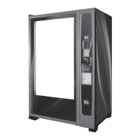
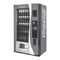
Why Royal Vendors Vending machine is not powering up after the door is closed?
- VVanessa BrightAug 21, 2025
Ensure the case holder is correctly folded and placed, and that there are no obstructions preventing proper closure.