
V
Victoria NortonAug 23, 2025
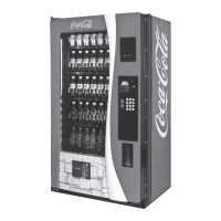
Why does my Royal Vendors Vending machine reject good coins?
- HHannah IbarraAug 23, 2025
Your Royal Vendors Vending machine may be rejecting good coins due to: * The coin return lever pressing down on the acceptor’s coin plunger. Ensure the changer is mounted correctly and the coin return lever is in the proper position. * The acceptor being dirty or foreign matter being in the path. Clean the acceptor or contact the distributor. * The coin changer being improperly tuned (if tunable). Contact the manufacturer for tuning. * A defective control board. Replace or test the control board.