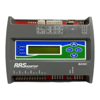
Ruskin Rooftop Systems (RRS) Economizer Basic
Model Quick Start Guide
Overview
To set up your RRS
®
Economizer controller, perform the
following steps:
1. Install the controller assembly with the included
installation instructions. Refer to the RRS Economizer
Basic Model Product Data and Installation Guide
(LIT-12013440).
2. Install additional sensors. The factory installs the
damper actuator and outdoor air sensor. You must
install any other sensors and output connections.
3. Configure the controller using the local display.
4. Run a Self-Test to verify proper operation.
Mounting the controller on a DIN rail
1. Horizontally mount a 20 cm (8 in.) section of 35 mm
(1.3 in.) DIN rail.
2. On the back of the controller, pull the two bottom
mounting clips outward (down).
Figure 1: Pull down lower mounting clips
3. Place the controller on the DIN rail.
4. Push the bottom mounting clips inward (up) to
secure the controller on the DIN rail.
Figure 2: Push up lower mounting clips
Wiring
1. Connect the sensors to the inputs on the Economizer
controller.
2. Use spade connectors to terminate the inputs and
outputs with the Spade termination.
Note: Temperature inputs accept a 10k
thermistor type 2 sensor. Humidity inputs
accept a 0 VDC to 10 VDC sensor.
3. Use the Economizer wiring harness to connect the I/
O with the pin connector termination type.
4. Install the sensors in the appropriate air stream.
*241014302066—*
24-10143-02066 Rev —
2019-09-18
(barcode for factory use only)
RK-ECO1001-0