arm roller is adjusted by tilting the pulley mounting block fore and aft and then securing the two 4-40
screws that hold the block to the arm. When adjusting the angle of the roller left or right, the
adjustment is made by carefully bending the vertical member of the threading arm so that the tape
travels in the middle of the roller or touches either flange
lightly.
Under no circumstances should the tape press against the flanges of the roller hard enough to
buckle or deform the tape. You will find that tilting the mounting block for and aft will adjust the
position of the tape on the roller when a tape is going in the forward direction; and in the reverse
direction, angling the arm left or right will affect the tape travel.
THREADING ARM SWITCHES
In addition to the rollers, the "in" and "out" microswitches should be adjusted to switch
approximately 3/16" prior to the arm reaching either its "out" position or its "home" position. The
threading arm is connected to the threading motor via a clutch(set to slip at 11 oz.), and the threading
motor will continue to run for a brief period after the arm "in" and arm "out" microswitches actually
switch.
TAPE BACKUP SUPPORT BLOCK EFFECTS DEFECT DETECTION
The black support block with the sapphire support rods also needs to be square to the transport panel.
Remove the detector to check the rods for squareness(90° to the panel.) The machine automatically
brings the detector backup block into position when tape is not threaded.
It is very important that the
rods that support the tape at the detector be perpendicular to the transport panel.
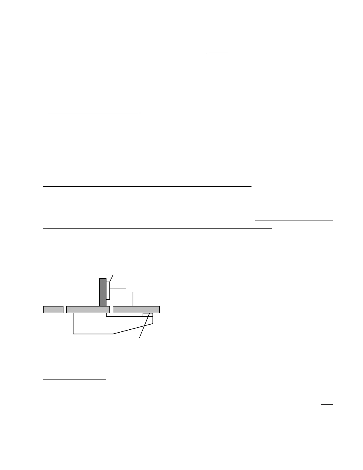
The following sketch shows the moveable cleaner and the tape back-up support block with the
sapphire rods.
Cleaner
90
Main panel
rods
Shims
.
This adjustment is made by adding or removing shim washers from the pivot bracket of the
moveable cleaner assembly underneath the transport panel.
CASSETTE HEIGHT
The height of the cassette is determined by the 6 support posts on the transport panel. These
hexagonal posts are fixed and not adjustable. For proper operation of the 4100 machine,
it is
imperative that the cassette be in contact with these support posts, not the carrier floor.. NOTE: The
large cassette has a total of six support posts. Obviously, because of variations in the large cassette
housing it is not totally flat and, therefore, if four of the six posts touch the cassette, that is sufficient
to support the cassette.
22
 Loading...