SPINDLE HEIGHT
The spindles of the machine that drive the reels inside the cassette should be at .990 inches above
the transport panel. This measurement is made from the top of the
spindle flange down to the top of
the transport panel. The spindle should be at this height, plus/minus .004 inches.
CASSETTE PLUNGER SENSORS
There are five plunger-type microswitch sensors underneath the cassette. These sensors sense
large/small reel hubs, metal/oxide tape and the erase tabs for small and large cassettes. For proper
operation, these microswitches should switch approximately 1/32" prior to the cassette coming down
on its support hex post. Also, check for the free action of the plunger. The plunger should not be
sticky and should return to its full upright position easily. DO NOT LUBRICATE THE
PLUNGERS, that causes them to stick due to the tight fit in the tube. Clean, dry plungers are
desired.
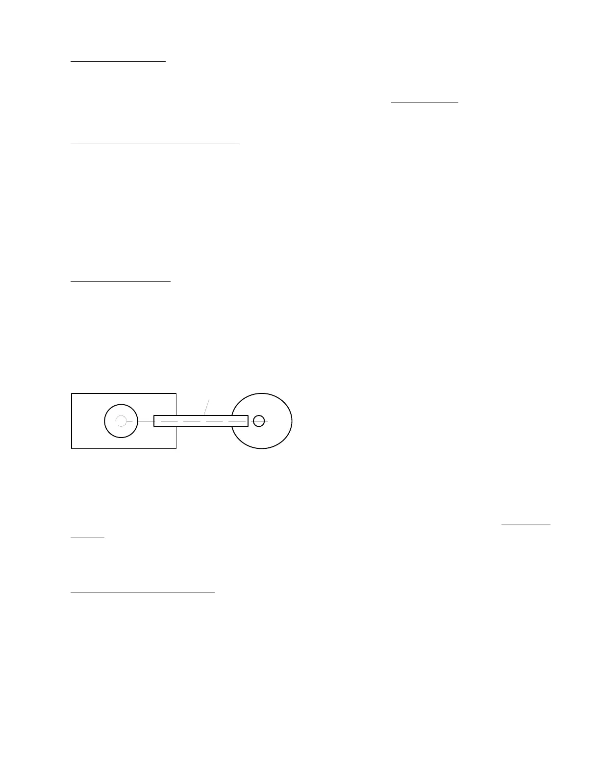
SPINDLE MOVERS
The spindles are moved to accommodate the large cassette via a gear motor and cam arrangement
with a straight arm linkage. The cam has a detente and two microswitches to stop the cam at the
appropriate position for the two sizes of cassettes. The arms of the microswitch may have to be bent
slightly (when installing a replacement switch) so that the switch operates reliably in the detente of
the cam.
Slide
Cam
Linkage
.
.
The linkage should be in a straight line from the pivot point of the cam to the spindle slide in the
"in" and "out" positions (180
°
apart). Check that both spindle cams are in the same relative position.
If they are not, the timing belt may have to be adjusted. This is accomplished by removing the
bearing roller that rides on the timing belt, cause slack in the belt and manually rotate the
right-hand
spindle until the proper orientation is achieved. Then reattach the timing belt bearing roller.
WARNING: Keep your hands and clothing out of the slides when they are operating.
CARRIER LIFT ASSEMBLY
The carrier is moved up and down by a gear motor with gears and linkage arms underneath panel.
The rotating arm is connected to the carrier via round linkages that are covered by a spring. When the
carrier is in the "down" position, the spring extends to add further down pressure, holding the cassette
in place. The rotating linkage should be approximately vertical when the carrier is in the up position
and straight down when the carrier is in the down position. The carrier lift motor is turned "on" and
"off" via two optical sensors on the back edge of the carrier floor. A tall "U" shaped bracket
interrupts the two optical sensor beams and causes the carrier to stop in the up and down position,
respectively. Once the "flags" of this "U" shaped bracket are trimmed to the proper the height at the
22
 Loading...